56 Chapter 3
Agilent 4072/4073 Preinstallation Guide, Edition 4
Wafer Probers and Connection with Testhead
Connecting with Testhead
Table 3-2 shows pin boards configuration If you ordered 28 of the Option 001 add one pin board.
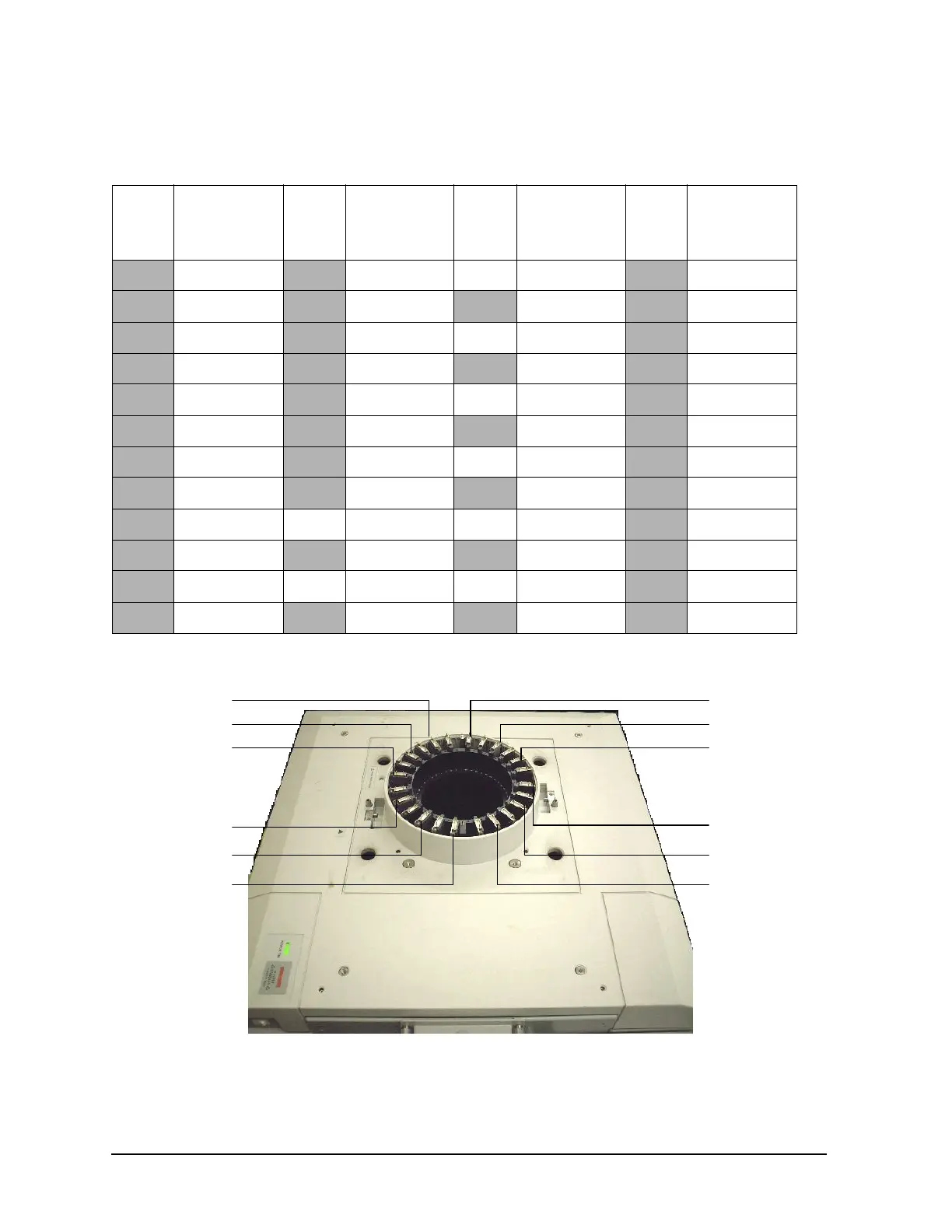
Figure 3-12 Pin board position in standard configuration
Table 3-2 Example of pin board configuration for 4072/4073 tester
Slot
no.
Pin board
installment
order
Slot
no.
Pin board
installment
order
Slot
no.
Pin board
installment
order
Slot
no.
Pin board
installment
order
11313 25 25 Empty 37 19
2114 4 26 7 38 10
31415 26 27 Empty 39 20
4A.I.16 A.I. 28 A.I. 40 A.I.
51517 27 29 Empty 41 21
6218 5 30 8 42 11
71619 28 31 Empty 43 22
8A.I.20 A.I. 32 A.I. 44 A.I.
9 17 21 Empty 33 Empty 45 23
10 3 22 6 34 9 46 12
11 18 23 Empty 35 Empty 47 24
12 A.I. 24 A.I. 36 A.I. 48 A.I.
pin board 4
pin board 8
pin board 12
pin board 16
pin board 20
pin board 24 pin board 28
pin board 32
pin board 36
pin board 40
pin board 44
pin board 48