The
EEPROM (A2U1)
stores the
unit
unique
data,
such
as
the
adjustment
data
and
the
operator
unique
data, such
as
the
operator
saved
measurement
setup
condition.
The
EEPROM
will
not
lose its
data
when
power
is
turned
o.
The
EEPROM
is
mounted
in
asocket
for easy
replacement.
Jumpers
and switches
set
the
4263B
's
conditions
.
Refer
to
Appendix
B
for
more information.
P
ower
Supply
Section
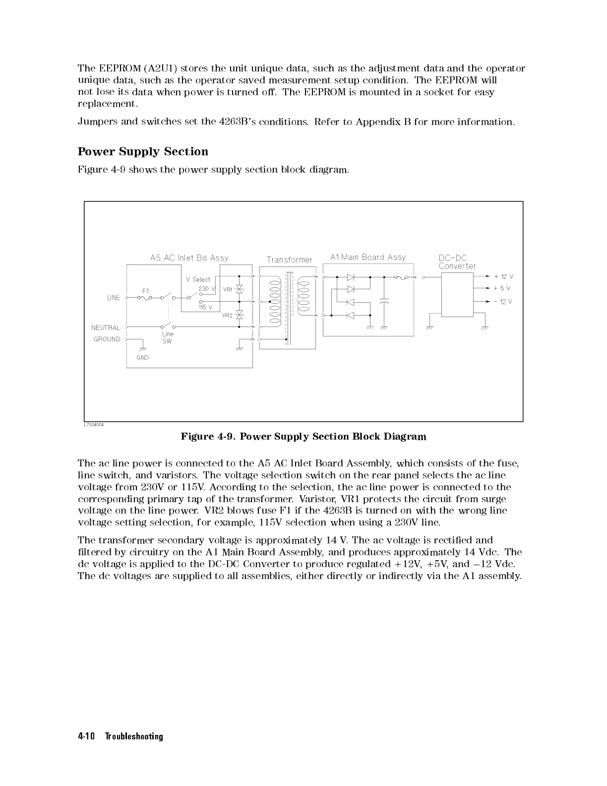
Figure
4-9 shows
the power
supply section
block diagram.
Figure
4-9.
P
ower
Supply
Section
Block
Diagram
The
ac
line
power
is
connected
to
the
A5
AC
Inlet Board
Assembly,
which consists
of
the
fuse
,
line
switch,
and
varistors
.
The
voltage
selection
switch
on
the
rear panel
selects the
ac line
voltage
from
230V
or
115V
.
A
ccording
to
the
selection,
the ac
line power
is connected
to
the
corresponding
primary
tap
of
the
transformer
.
V
aristor
,
VR1
protects the
circuit from
surge
voltage
on
the
line power
.VR2
blows fuse
F1 if
the
4263B
is
turned
on
with
the
wrong
line
voltage
setting selection,
for example
, 115V
selection when
using a
230V line
.
The transformer secondary voltage is approximately 14 V
. The ac voltage is rectied and
ltered
by circuitry on the A1 Main Board Assembly
, and produces approximately 14 Vdc
. The
dc voltage
is applied to the DC-DC Converter to produce regulated +12V
,+5V
, and
0
12 Vdc
.
The dc voltages are supplied to all assemblies
, either directly
or indirectly via the A1 assembly
.
4-10 Troubleshooting

 Loading...


