Chapter 5: Troubleshooting
To check the SVGA display board video signals
5–22
To check the SVGA display board video signals
The video signals are checked on the 40-pin connector J103 on the SVGA display board A5. Use
a 100-MHz, general-purpose oscilloscope, such as the Agilent Technologies 54600B, to verify the
signals. Even-numbered pins are on the top side of the connector. The video signals are present
during the system boot process before the backlights come on. If the signals are not present,
suspect the display card. If the signals are present and the backlights are on, suspect the flat-
panel display as the problem.
Table 5-5
Video Signals
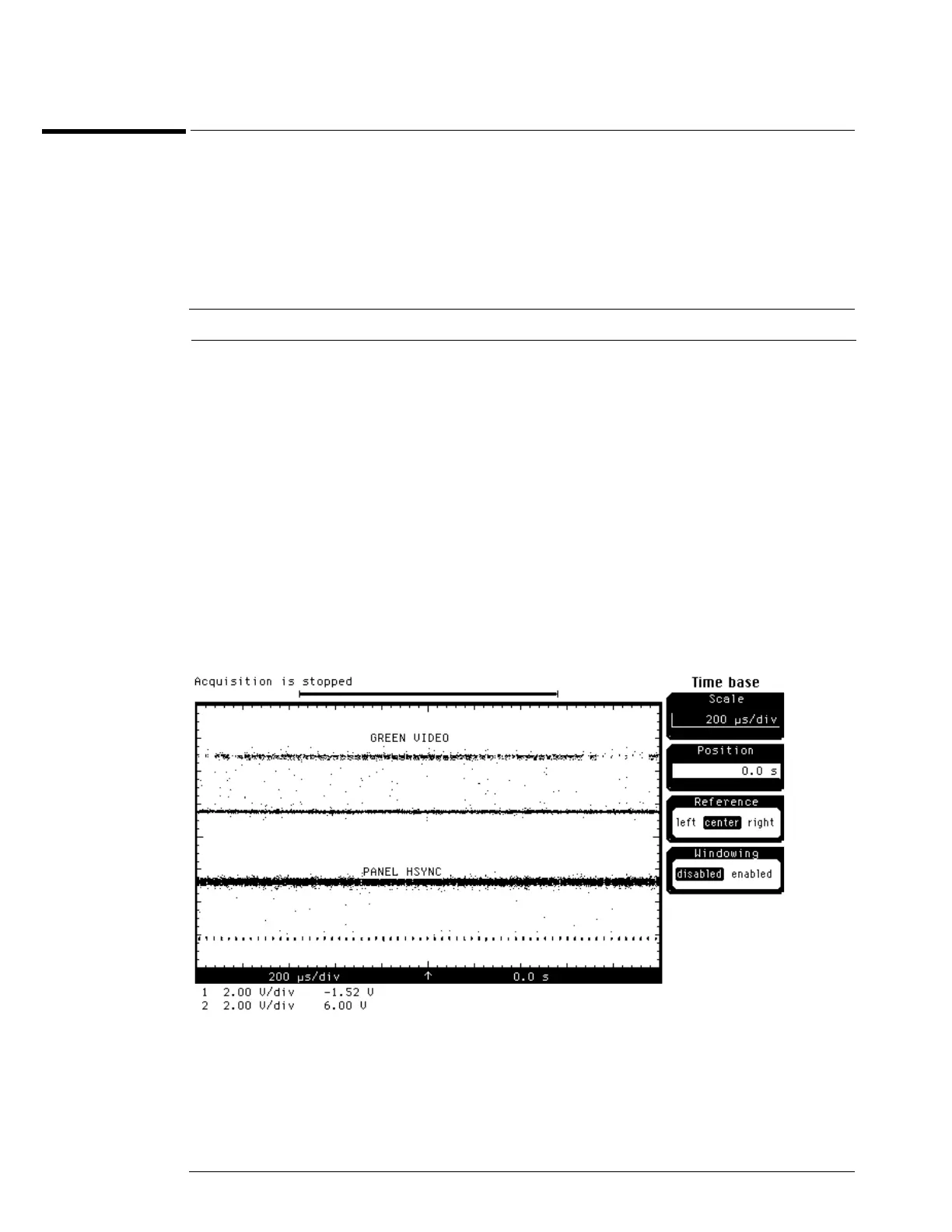
Figure 5-8
Video Signals
Pin Number Signal
1-2 +3.3 V
3, 5-6 NC
4, 7-9, 11, 15, 19, 23, 27, 31, 35, 38, 40 Ground
12-14, 16-18 Blue video
20-22, 24-26 Green video
28-30, 32-34 Red video
10 Panel enable
36 Panel HSync
37 Panel VSync
39 Panel Clk