Chapter 5: Troubleshooting
Power Supply Trouble Isolation
5–13
Power Supply Trouble Isolation
These trouble isolation instructions help isolate the problem to the assembly level when the
power supply is not operating. Because of advanced power supply protection features, the
problem may not be with the supply itself, and therefore you will need to work through the
procedure systematically to determine the source of the fault.
A
Check the power supply voltages.
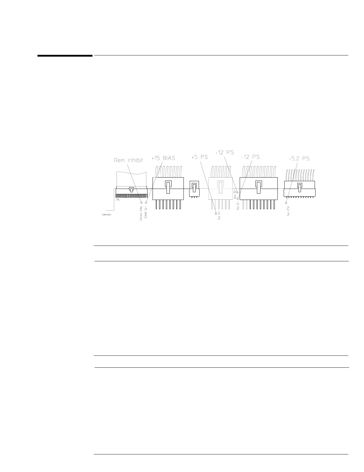
You check the power supply voltages on the acquisition board, A13. See figure 5-3 for the location
of these test points. Table 5-2 shows the allowable range of power supply voltages.
Figure 5-3
Power Supply Voltage Test Locations (A13)
Table 5-2 Power Supply Voltage Limits
B
Turn off the power and measure the power supply resistances to ground to check for
shorted supply lines.
You can probe the test points on A13, shown in figure 5-3, for this resistance check. Table 5-3
shows the characteristic resistance values for the Agilent Technologies 54835A/45A oscilloscope.
Table 5-3 Approximate Resistance Values, Each Power Supply to Ground
Supply Voltage Specification Limits
+5.1 V ± 0.1 V +5.0 V to +5.2 V
-5.2 V ± 0.1 V -5.1 V to -5.3 V
+12.2 V ± 0.3 V +11.9 V to +12.5 V
-12.2 V ± 0.3 V -11.9 V to -12.5 V
Supply Approximate Resistance to Ground
+12 V 300Ω
–12 V 180Ω
–5.2 V 10Ω
+5.1 V 50Ω