Chapter 6: Replacing Assemblies
To remove and replace the cover
6–4
To remove and replace the cover
Use these steps to remove and replace the cover. When necessary, refer to other removal
procedures.
1
Disconnect the power cable.
2 Disconnect all scope probes and BNC input cables from the front panel.
3 Disconnect any other cables, such as mouse, keyboard, printer, or GPIB cables.
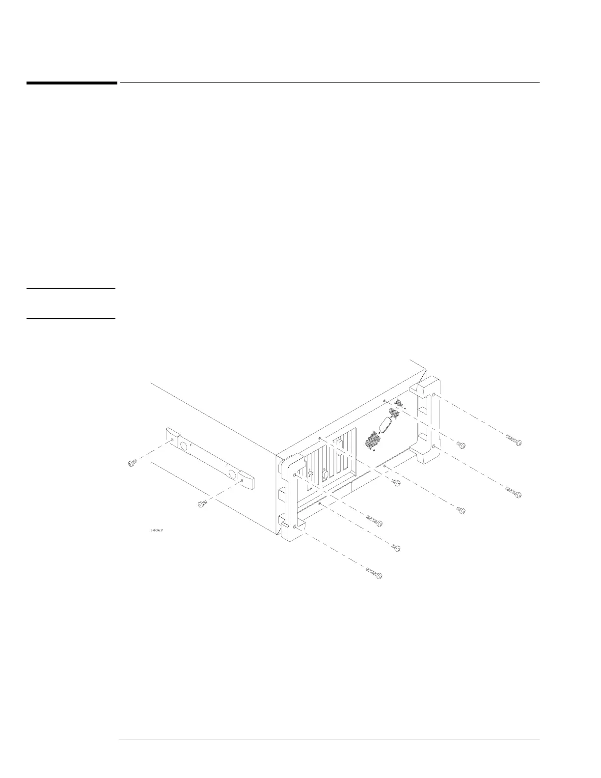
4 Remove the two Torx T15 screws securing the side handle.
5 Remove the four Torx T15 screws that secure the rear feet (two in each foot).
6 Remove the four Torx T15 screws that secure the cover to the chassis.
7 Set the unit on its side. Carefully slide the cabinet off of the frame by pulling the front
panel and the cover away from each other.
8 To replace the cover, reverse the above procedure.
Be sure to keep ribbon cables out of the way when replacing the cover, particularly the flex cable
and connector for the AutoProbe assembly at the bottom front of the oscilloscope.
CAUTION PROPERLY TIGHTEN HANDLE AND SCREWS!
Tighten the side handle and rear feet screws to 2 Nm (18 in-lbs).
Figure 6-1
Cover Fasteners