Chapter 6: Replacing Assemblies
To remove and replace the AutoProbe assembly
6–6
To remove and replace the AutoProbe assembly
Use this procedure to remove and replace the AutoProbe assembly. When necessary, refer to
other removal procedures.
1
Disconnect the power cable and remove the cover.
2 Remove the AutoProbe connector assembly, the subpanel, and the probe connector
assembly that fits around the front-panel BNC connectors, by doing the following:
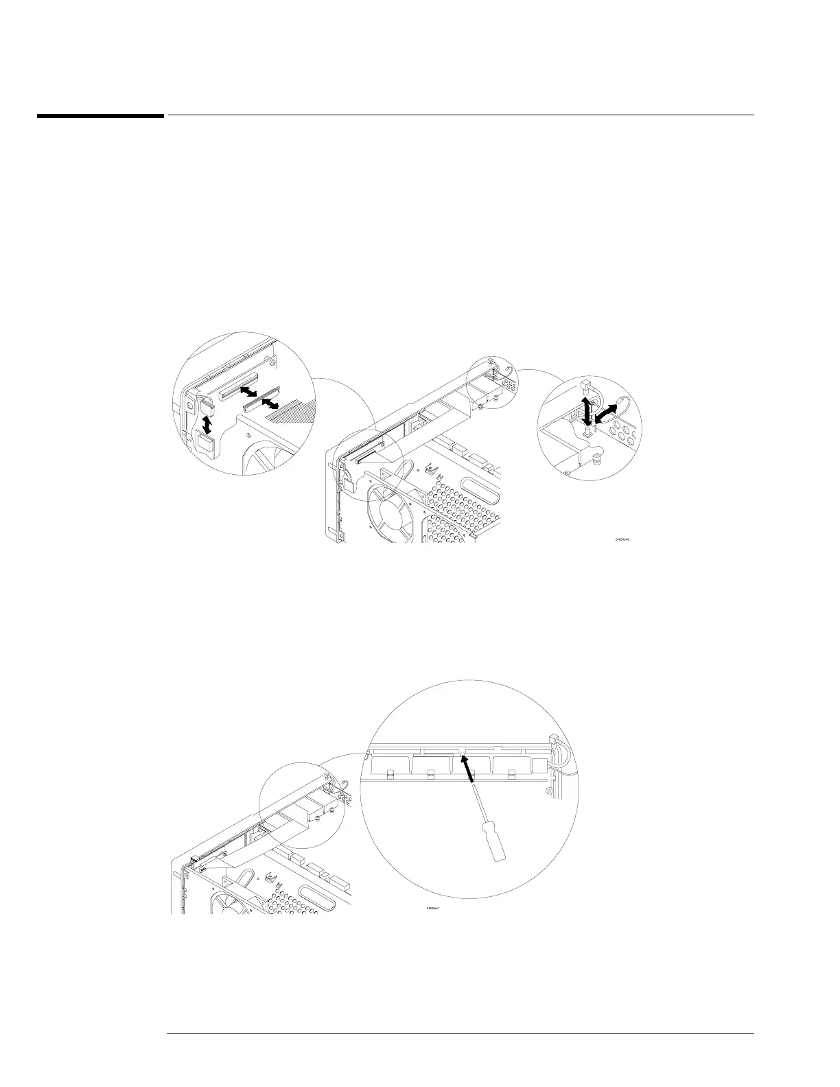
a Disconnect the mylar ribbon cable W13 from the Probe Power and Control Board, A11.
See “To disconnect and connect Mylar flex cables” in this chapter.
Figure 6-4
Disconnecting W13
b Locate the access hole in the front-panel assembly below and almost between channel
two and channel three attenuators.
Figure 6-5
Access Hole