Chapter 5: Troubleshooting
To configure the motherboard jumpers and set up the BIOS
5–33
The jumpers you must check are J2, J11, J12, J21, J24, J25, J37, and J39. In addition, you need
to ensure that the CPU fan is connected to J46 once the CPU is installed. Failure to connect the
fan will cause the CPU to overheat and malfunction.
CAUTION AVOID DAMAGE TO THE CPU BY CORRECTLY CONFIGURING THE JUMPERS!
You must configure J2, J11, J12, and J21 before installing the CPU and applying power to the
motherboard. Failure to configure these jumpers correctly may damage the CPU.
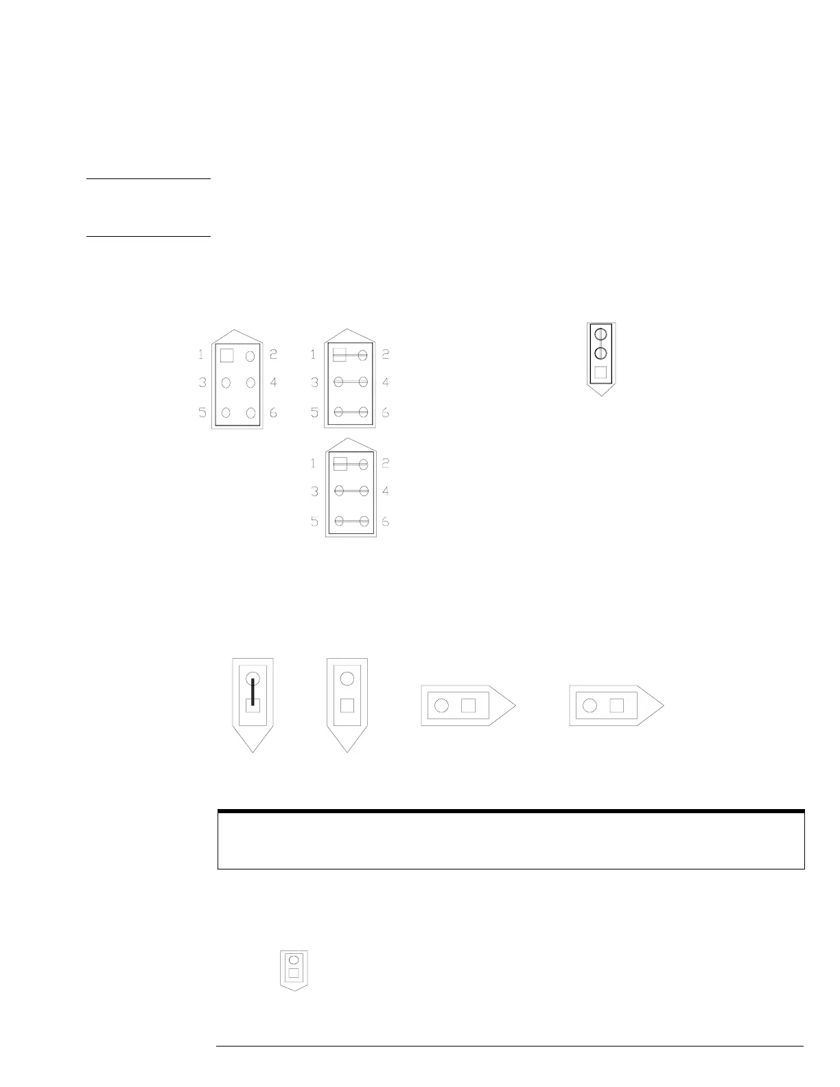
• To configure the jumpers, set J2, J11, J12, and J21 as shown in the following figure. Note
that all pairs of pins on J12 and J21 are shorted; all pins on J2 are open.
• The processor must be configured for a 100 MHz clock speed by setting jumpers J24,
J25, J37, and J39 as shown in the following figure. Note that the pins on J25 are shorted
and the pins on J24, J37, and J39 are open.
• To connect the fan, connect the fan cable to J46. The colored fan lead must connect to
Pin 1.
A 100-MHz Clock Is Required
The AMD-K5-PR133 processor requires a 100 MHz clock. The processor part number is printed on the top
of the part.
J21J2
J11
J12
J37
J39
J25 J24
J46
Pin 1
+12V
GND