Installation
8-13
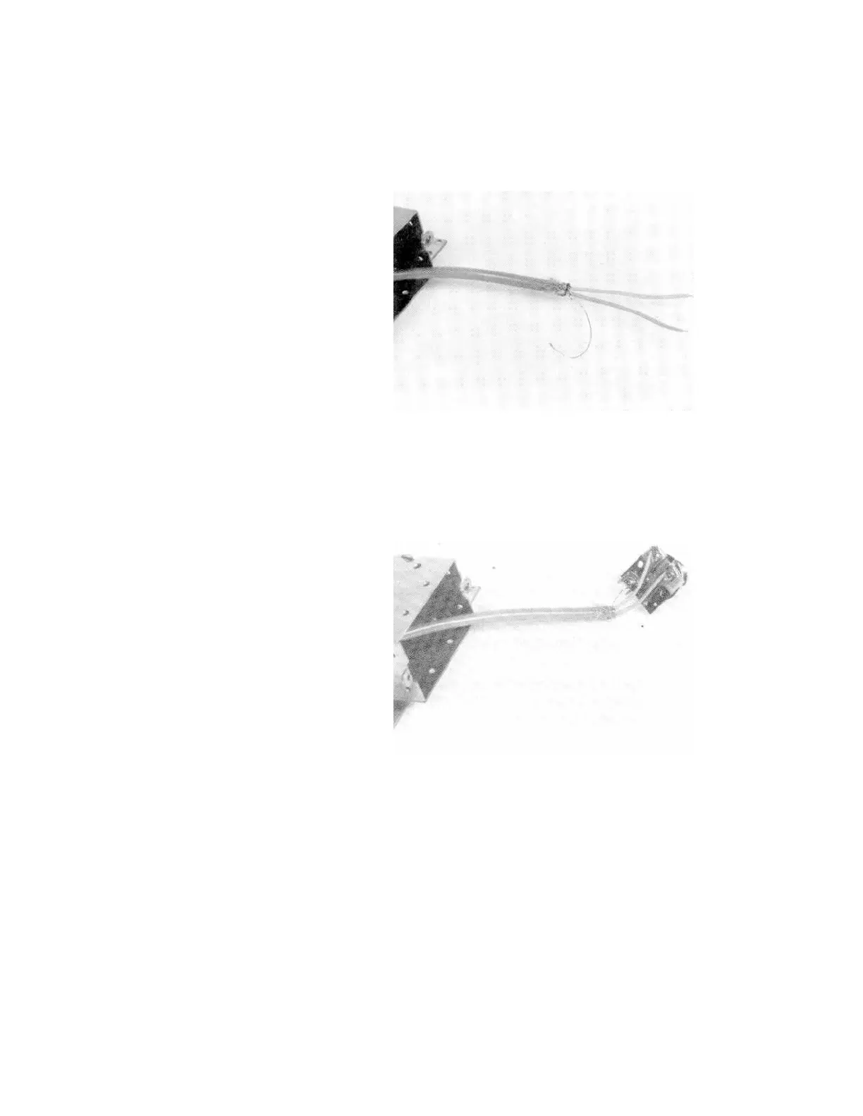
back the rest of the shield—at least 1.3 cm (1/2 inch)—OVER THE
CABLE INSULATION.
d. Remove the foil and filler strips from the cable end and separate the
PINK, BLUE, and drain wires.
e. Attach the drain wire to the GND terminal connector on the PC board/
SDN connector assembly. Wrap the drain wire completely around the
terminal screw.
f. With the drain wire extended directly below the PC board/connector
assembly, lay the PINK and BLUE wires over their respective terminal
connectors and trim the ends at the appropriate length to allow the
bare end of the PINK and BLUE wires to be wrapped clockwise three-
quarters of the way around the terminal screw.
g. Strip off the insulation from the wire ends. Using long nose pliers, bend
the bare wire end into a loop and attach to the appropriate terminal.
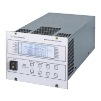
h. Place the PC board/SDN connector assembly into the shield cover and
secure it in place using the knurled ring. Make sure the connector fits