Procedures
8-24
desired length and terminated at the installation site with the associated
colored connector. Raw LDC and up/downstream connectors are available
also to fabricate LDCs as required.
Table 8-3: Variable Length LDCs
Instructions for terminating the SDN connector onto the open end of the
LDC are specified in detail on page 8-25. The length of the LDC is subject
to the restrictions and limitations specified on page 8-4.
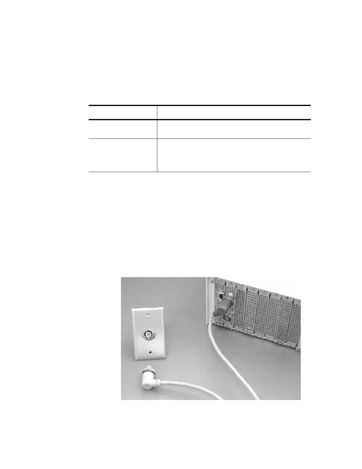
Connect LDC from Wall Box to Instrument(s)
Connectors on the local distribution cables are mechanically keyed and
color-coded to prevent erroneous connection. The color on the connector
end of the LDC is either GRAY (DOWNSTREAM) or BROWN (UPSTREAM).
The upstream cable direction is from the instrument(s) towards the wall
box (ACC) and the downstream cable direction is from the wall box
towards the instrument(s). The LDC connectors and receptacles are
illustrated in Figure 8-3.
Figure 8-3. LDC Connections from Bedside Instruments to Wall Box
Variable Length LDC Agilent Technologies Part Number
15.2 meters (50 ft.) 78599AI-J50. Includes molded connector one end and
downstream connector to be installed on other end.
15.2 meters (50 ft.) 78599Al-J54. Includes one 15.2 cm (50 ft.) length of
unterminated LDC.
78599AI-J52. Includes two SDN connectors—upstream
and downstream.