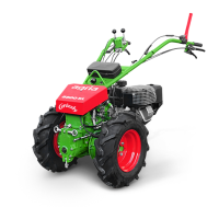
32 agria Multi-Purpose Machine 400P
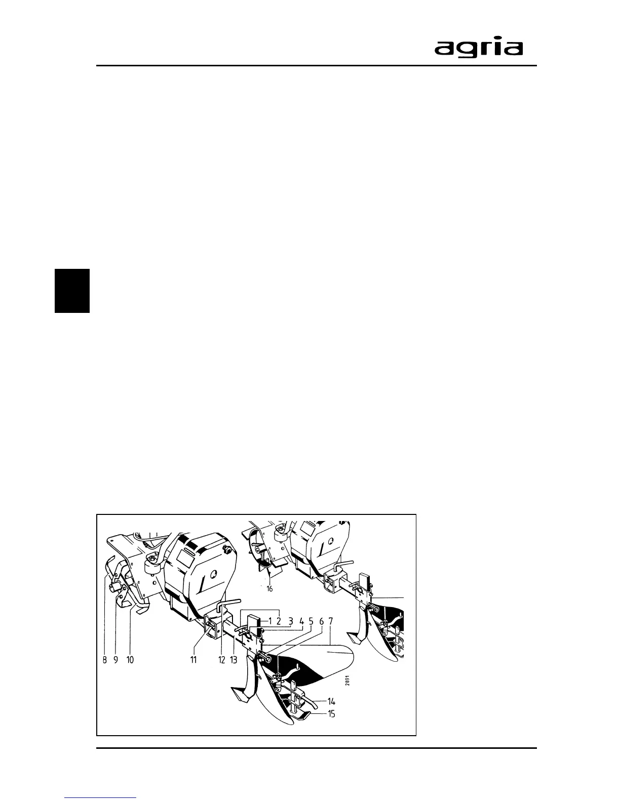
3. Devices and Operating Elements
1 Ridger
2 U-pin
3 W-clip
4 Clamping screw
(ridger adjustment)
5 Set screw (ridging depth
adjustment)
6 Clamping screw (ridging
width adjustment)
7 Mouldboard
8 Hoeing tine
9 Hoeing tine attachment
bolt
10 Hoeing tine
11 Set screw
(adjustment of float)
12 Pin
13 Coupling bar
14 Clamping screw
(slade adjustment)
15 Slade
3
Ridger
Required Accessories
1 coupling bar ........ Item no. 0440 111
1 ridger................... Item no. 0252 011
alternatively
1 set of
strake wheels ......... Item no. 0120 011
Assembly:
l
Remove any add-on hoeing tools.
l
Remove the outer hoeing tines (8
and 10) from each end of the hoeing
shaft and swap sides with the tines
pointing inwards (see figure below).
This way the hoeing width is adjusted
to 36cm without any special hoeing
tools needed.
l
Mount the guard discs.
l
Remove the depth bar and install the
coupling bar (13) instead.
l
Insert the ridger stem (1) into the leg
pocket. Insert the U-pin (2) as shown
and secure it with a W-clip.
l
To tilt the ridger adjust it with hex set
screw (5). Then move the ridger (1) into
the desired tilting position – the more
the ridger tilts backwards the deeper is
the working depth.
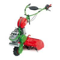
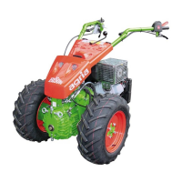
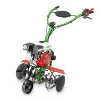
Strake Wheels
To improve tractive power and ridging
quality in hoed soil use strake wheels
(accessory no. 0120 011) (16) instead
of hoeing tools.
Like the hoeing tools, strake wheels are
attached with hex bolts which are in-
serted through the hub and hoeing shaft
borings.
Ridging
For ridging operation start the power hoe
as described in the paragraph on hoe-
ing.
l
Correct the ridging depth by adjust-
ing the set screw (5) in the leg pocket
or the slade (15) and the clamping
screw (14).
l
Set the ridging width by adjusting the
mouldboards (7) and the clamping
screw (6).
l
The desired/required degree of float-
ing is adjusted with the set screws (11)
and the lock nuts.