S04C S04C 6-46-4
OBSERVERA
Returanslutningen för hydraulham-
maren sitter på lyftarmens vänstra
insida.
VARNING
Läs säkerhetsbestämmelserna,
som finns i den bifogade bruksan-
visningen för hydraulhammaren, för
att förebygga olyckor och vid
underhållsarbeten.
ANMÄRKNING
Typskylten sitter på baksidan av
monteringsplattan (6-5/pil).
6.1.4 Lastkrok
ANMÄRKNING
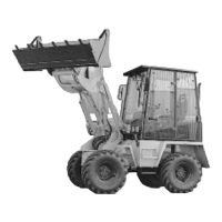
- Figur 6-6 visar maskinen med last-
kroken.
- Monteringen och demonteringen
utförs på samma sätt som för
skopan (avsnitt 6.1.1).
VARNING
- De båda bultarna på snabbfästet
måste sitta i fästhålen på båda
sidor i skopupphängningen och
sticka ut tydligt på sidorna.
- Kontrollera att säkerhetsspärren
på lastkroken fungerar som den
skall.
ANMÄRKNING
Typskylten sitter på ovansidan av
armen (6-6/pil).
CAUTION
The return-flow connection for the
hydraulic hammer is on the left inner
side of the shovel arm.
DANGER
Safety regulations for prevention of
accidents as well as details regar-
ding maintenance can be taken from
the operation manuel delivered with
the hydraulic hammer.
NOTE
The type plate is on the rear side of
the mounting plate (6-5/arrow).
6.1.4 Crane hook
NOTE
- Figure 6-6 shows the loader with
a crane hook.
- The fitting and dismounting is
carried out analogue to the
bucket (section 6.1.1).
DANGER
- Both the bolts of the quick-change
device must be found on both
sides in the location bores of the
suspension for the crane hook.
The bolts must distinctly protrude
at the sides.
- Check safety flap of crane hook
for functioning.
NOTE
The type plate is on the top side of
the jib (6-6/arrow).
OBSERVERA
Returanslutningen för hydraulham-
maren sitter på lyftarmens vänstra
insida.
VARNING
Läs säkerhetsbestämmelserna,
som finns i den bifogade bruksan-
visningen för hydraulhammaren, för
att förebygga olyckor och vid
underhållsarbeten.
ANMÄRKNING
Typskylten sitter på baksidan av
monteringsplattan (6-5/pil).
6.1.4 Lastkrok
ANMÄRKNING
- Figur 6-6 visar maskinen med last-
kroken.
- Monteringen och demonteringen
utförs på samma sätt som för
skopan (avsnitt 6.1.1).
VARNING
- De båda bultarna på snabbfästet
måste sitta i fästhålen på båda
sidor i skopupphängningen och
sticka ut tydligt på sidorna.
- Kontrollera att säkerhetsspärren
på lastkroken fungerar som den
skall.
ANMÄRKNING
Typskylten sitter på ovansidan av
armen (6-6/pil).
CAUTION
The return-flow connection for the
hydraulic hammer is on the left inner
side of the shovel arm.
DANGER
Safety regulations for prevention of
accidents as well as details regar-
ding maintenance can be taken from
the operation manuel delivered with
the hydraulic hammer.
NOTE
The type plate is on the rear side of
the mounting plate (6-5/arrow).
6.1.4 Crane hook
NOTE
- Figure 6-6 shows the loader with
a crane hook.
- The fitting and dismounting is
carried out analogue to the
bucket (section 6.1.1).
DANGER
- Both the bolts of the quick-change
device must be found on both
sides in the location bores of the
suspension for the crane hook.
The bolts must distinctly protrude
at the sides.
- Check safety flap of crane hook
for functioning.
NOTE
The type plate is on the top side of
the jib (6-6/arrow).
 Loading...