S04C S04C 6-86-8
6.2.2 Front-end excavator
NOTE
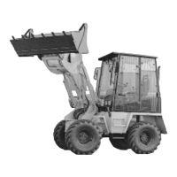
Figure 6-16 shows the front-end
excavator at its maximum horizontal
reach at ground level.
Mounting
Mounting is carried out analogous
to the multi-purpose bucket ((section
6.2.1 (1)...(10)).
DANGER
Both the bolts of the quick-change
device must be found on both sides
in the location bores of the suspen-
sion for the front-moundet back-
hoe. The bolts must distinctly pro-
trude at the sides.
NOTE
After mounting the front-end exca-
vator, switch the ball block valve on
the tip cylinder (6-17/arrow) to the
“front end excavator” position (ver-
tical). This throttles the tip cylinders
working speed.
Dismounting
Dismounting is carried out analo-
gous to the multi-purpose bucket
(section 6.2.1).
NOTE
- After dismounting the front-end
excavator, switch the ball block
valve on the tip cylinder (6-17/
arrow) to the “bucket” position
(horizontal).
- The type plate is on the right hand
side of the stanchion rod in the
vicinity of the mounting plate.
6.2.2 Grävskopa
ANMÄRKNING
Figur 6-16 visar grävskopan i maxi-
malt utsträckt position i markläge.
Montering
Monteringen går till på samma sätt
som med universalskopan ((avsnitt
6.2.1 (1) till(10)).
VARNING
De båda bultarna på snabbfästet
måste sitta i fästhålen på båda
sidor i skopupphängningen och
sticka ut tydligt på sidorna.
ANMÄRKNING
Efter monteringen av grävskopan
skall kulblocksventilen vid tippcylin-
dern (6-17/pil) kopplas om till läge
grävskopa. Därigenom minskas
tippcylinderns arbetshastighet.
Demontering
Demonteringen går till på samma
sätt som för universalskopan
(avsnitt 6.2.1).
ANMÄRKNING
- Efter demonteringen av grävsko-
pan skall kulblocksventilen till tipp-
cylindern (6-17/pil) kopplas om till
läge skopa (vågrätt).
- Typskylten sitter på höger sida
om handtaget, i närheten av mon-
teringsplattan.
6.2.2 Front-end excavator
NOTE
Figure 6-16 shows the front-end
excavator at its maximum horizontal
reach at ground level.
Mounting
Mounting is carried out analogous
to the multi-purpose bucket ((section
6.2.1 (1)...(10)).
DANGER
Both the bolts of the quick-change
device must be found on both sides
in the location bores of the suspen-
sion for the front-moundet back-
hoe. The bolts must distinctly pro-
trude at the sides.
NOTE
After mounting the front-end exca-
vator, switch the ball block valve on
the tip cylinder (6-17/arrow) to the
“front end excavator” position (ver-
tical). This throttles the tip cylinders
working speed.
Dismounting
Dismounting is carried out analo-
gous to the multi-purpose bucket
(section 6.2.1).
NOTE
- After dismounting the front-end
excavator, switch the ball block
valve on the tip cylinder (6-17/
arrow) to the “bucket” position
(horizontal).
- The type plate is on the right hand
side of the stanchion rod in the
vicinity of the mounting plate.
6.2.2 Grävskopa
ANMÄRKNING
Figur 6-16 visar grävskopan i maxi-
malt utsträckt position i markläge.
Montering
Monteringen går till på samma sätt
som med universalskopan ((avsnitt
6.2.1 (1) till(10)).
VARNING
De båda bultarna på snabbfästet
måste sitta i fästhålen på båda
sidor i skopupphängningen och
sticka ut tydligt på sidorna.
ANMÄRKNING
Efter monteringen av grävskopan
skall kulblocksventilen vid tippcylin-
dern (6-17/pil) kopplas om till läge
grävskopa. Därigenom minskas
tippcylinderns arbetshastighet.
Demontering
Demonteringen går till på samma
sätt som för universalskopan
(avsnitt 6.2.1).
ANMÄRKNING
- Efter demonteringen av grävsko-
pan skall kulblocksventilen till tipp-
cylindern (6-17/pil) kopplas om till
läge skopa (vågrätt).
- Typskylten sitter på höger sida
om handtaget, i närheten av mon-
teringsplattan.
 Loading...