Chapter 2: Installation
Complete Electrical Connections
Page 32
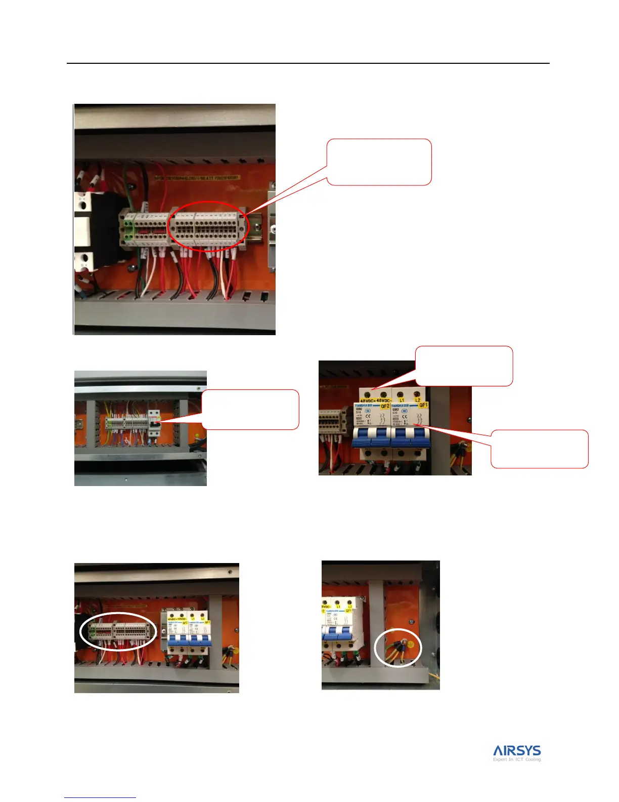
2. Bring the control harness (item 4 in Table 5 on page 10) from the controller box to the WPU by passing it
through the hole in the shelter. Make the thirteen wire connections inside the WPU.
3. Connect the power cables from the power plant to each WPU.
Note: If the ASLLC.2.48 is chosen and the HVAC is equipped with DC EC supply fan, connect the power cables as
shown in the picture below.
4.Complete the connections.
Control harness
connections in the
WPU
Prime power
connections to WPU
48VDC power
connections to WPU
Prime power
connections to WPU