Chapter 2: Installation
Complete Electrical Connections
Page 29
Electrical Connection to Controller Box
Follow these steps to complete the connections:
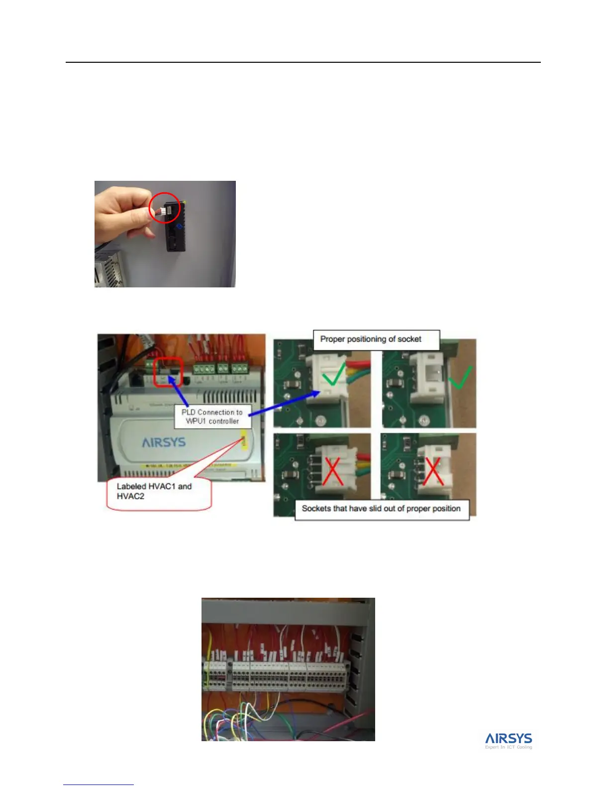
1. Open the controller box.
2. Ensure the PLD cable is FIRMLY plugged into the user interface terminal located on the inside of the
controller box cover.
3. Ensure the other side of the PLD cable is FIRMLY plugged into the HVAC1 controller board terminal J7
as shown below.
4. Connect the WPU 1 control harness in the controller box. When this is complete, do the same for the WPU
2 control harness. Refer to Fig 15. System Schematic Diagram on page 21.