Chapter 2: Installation
Complete Electrical Connections
Page 28
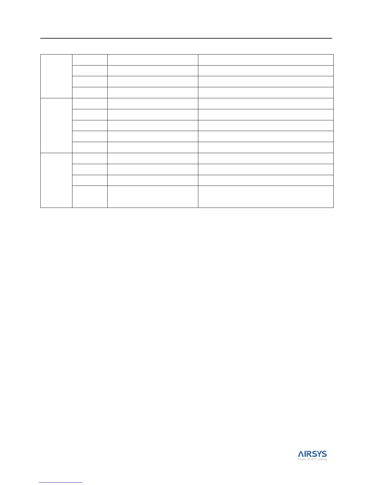
Table 12: The control harness terminal identification of ASLLC.2.48
The voltage between terminal 1 & terminal 12 is 48Vdc
HVAC prime power power alarm
Between terminal 2 & terminal 12 is NC
The voltage between terminal 3 & terminal 12 is 48Vdc
Common terminals for alarms
Between terminal 6 & terminal 5 is NC
Between terminal 7 & terminal 5 is NC
PF1, air pressure differential switch
Between terminal 8 & terminal 5 is NC
PF2 or PF2&3, output the operating status
of supply fans to controller
Between terminal 9 & terminal 5 is NC
(The system which installed two DC fans need PF2 &PF3)
YE, input signal to air damper actuator
The signal voltage for damper actuator, 0~10Vdc
MF2, input signal to supply fan
The signal voltage for supply fan, 0~10Vdc
Power supply for Damper actuator
Power supply for Damper actuator, the voltage between terminal
12 & terminal 13 is 24Vdc.
Refer to Figure 15: System Schematic Diagram on page 21.