Chapter 2: Installation
Complete Electrical Connections
Page 27
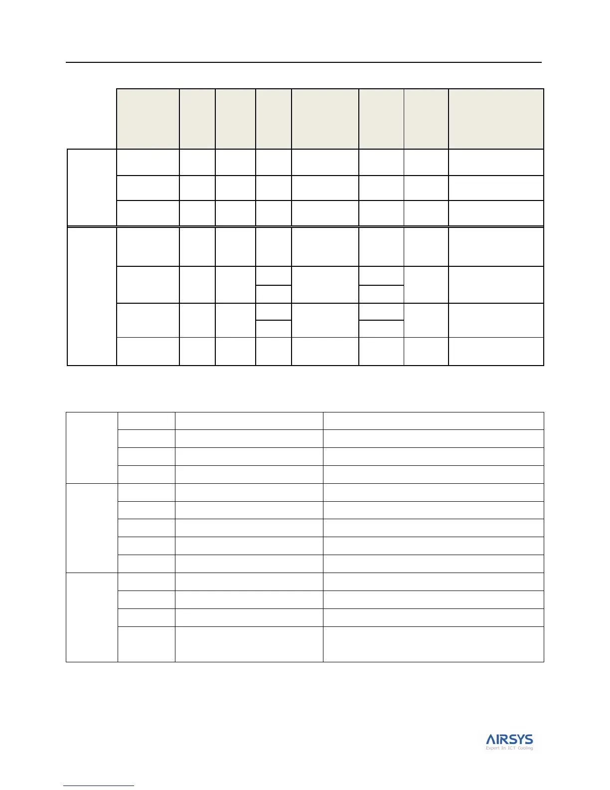
Table 10: Alarm Connections
(S=software via
PLD)
(HW= Hard
Wired)
Form C
Contact
Alarm
INPUTS
Remove factory jumper
prior to connecting alarm
input
Connected to Gen-Run
signal
Only when using DC Fail-
Over Box: ASPCB.2
Form C
Contact
Alarm
OUTPUTS
High/low
temperature
alarm
Can connect in series for
NC or in parallel (NO) with
analog High/low Temp
thermostats in many sites.
Indicates Mechanical
Cooling disabled until
problem addressed on site
Indicates Mechanical
Cooling disabled until
problem addressed on site
Indicates compressors
running in both Lead & Lag
WPUs simultaneously
Control Harness Terminal Identification
Table 11: The control harness terminal identification of ASLLC.2
The voltage between terminal 1 & terminal 4 is 240Vac
The voltage between terminal 2 & terminal 4 is 240Vac
The voltage between terminal 3 & terminal 4 is 240Vac
Common terminals for alarms
Between terminal 6 & terminal 5 is NC
Between terminal 7 & terminal 5 is NC
PF, air pressure differential switch
Between terminal 8 & terminal 5 is NC
MF2, output the operating status of supply
fan to controller
Internal overload protection, it is NC.
YE, input signal to air damper actuator
The signal voltage for damper actuator, 0~10Vdc
MF2, input signal to supply fan
The signal voltage for supply fan, 0~10Vdc
For DC power supply and signal voltage
Power supply for Damper actuator, the voltage between terminal
12 & terminal 13 is 24Vdc.