Chapter 3: System Operation
System Diagnostics
Page 57
System Diagnostics
The information provided in this section may be useful during the troubleshooting of issues that arise during
operation of the system. Two types of information are provided:
A description of the input and output ports of the controller
A description of all factory settings and how they can be viewed and modified
Port Definitions
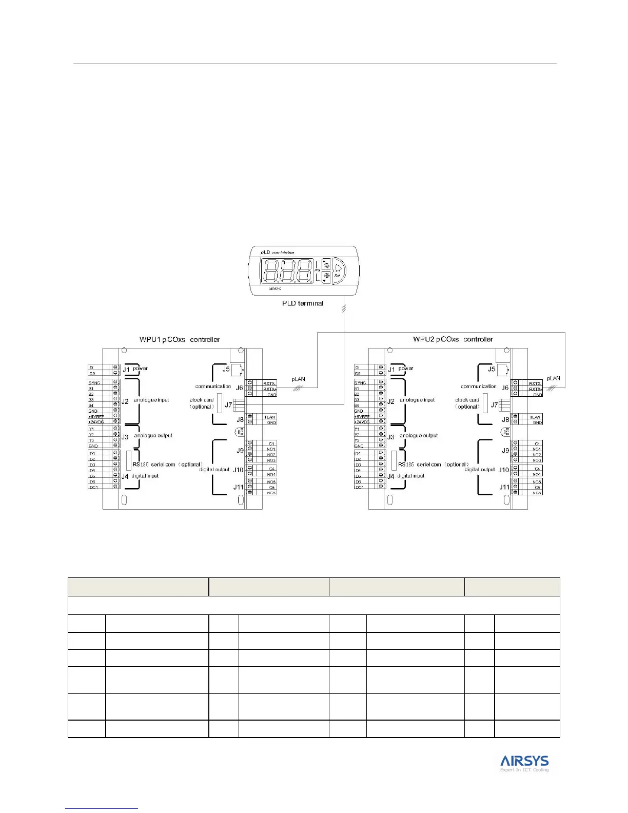
Figure 22 is a schematic drawing of the controller module (PLC) ports.
Figure 22: pCOxs Controller Hardware Structure
Table 23 lists the input and output ports of the unit.
Table 23: Port Values
pCOxs-1 (Main, Address 1: WPU 1)
High/low temperature
alarm (NC)