Chapter 2: Installation
Verify System Operation
Page 38
Verify the sensor readings
All the sensors are factory calibrated before shipping. However, it is essential to verify that all sensors are properly
connected.
1. Press Up and Down together to return to the default display (indoor temperature)Press Up or Down to
scroll through the main menu
2. Press Sel to display reading for Humidity, Outdoor Temp, and Supply Air Temp
3. Scroll to and Press Sel The pLD will display StP (temperature setpoint)
4. Press Down until rt2 (Room temp 2) is displayed, press Sel to display backup temp sensor reading
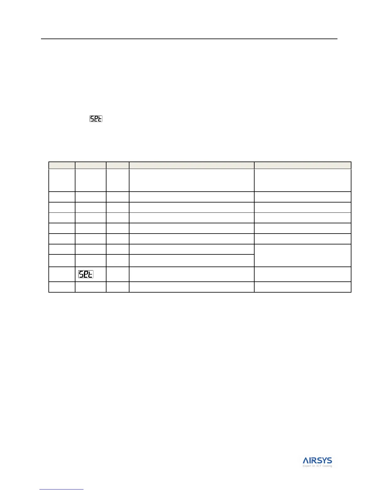
Table 15: ASLLC Main Menu
Note: Sensors can be calibrated in the C menu. See section Accessing the C Menu on page 59 for detail.
Verify Input and Output Alarms
1. Verify Generator Signal (A28 alarm)
Important: Incorrect signal from generator will prevent the 2nd unit from cooling
a. From rt2 press Down until D5A is displayed, Press Sel to display generator status
b. If the generator is not running or generator signal is not wired, your screen should display OFF
c. Press the Sel button to return to D5A
2. Verify Smoke/Fire Alarm Signal (A05 alarm)
a. Press the test bottom on the smoke/fire detector. The system should completely shut down (Fans
and compressors off, damper closed, A05 alarm code will be displayed).
b. The Smoke/fire Alarm is connected to 41 and 5 on the controller terminal. If the smoke/fire
detector does not have a test bottom, disconnect the jumper on 41; the system should shut down.
Current indoor temperature; default display
Press UP and DOWN together to get
to the indoor temp. Press DOWN to
access other menus.
Set comfort mode indoor temperature
Hint: use the “Huff Test”
Unit 1 Supply air temperature
Important: Wrap hand around supply
air sensor to verify unit 1 sensor is
mounted on unit 1 and vice versa
Unit 2 Supply air temperature
Access other menus for viewing and modifying
preconfigured system parameters