Chapter 3: System Operation
User Interface Introduction
Page 44
Chapter 3: System Operation
This chapter describes how to use the PLD interface to execute the functions needed during standard operation. In
addition, reference information is supplied on all of the factory default settings. This information may be useful
during troubleshooting and in conversations with technical support.
The following topics are covered:
Using the Main Menu to execute basic functions
Understanding alarms that may occur and clearing alarm history
Additional system diagnostic information
User Interface Introduction
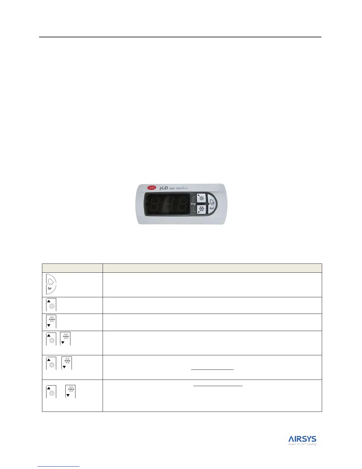
The units are controlled using a simple interface with an LED display and three buttons.
Figure 21: PLD User Interface
Button actions are described in Table 16: PLD Button Actions.
Table 16: PLD Button Actions
Confirm selection or display value.
When the LED is on, indicates that an alarm has been triggered.
Increase value or go back to previous parameter.
When flashing (slow flash), there is no Mechanical Cooling on HVAC 1 (aka Lockout)
Decrease value or go to next paramter.
When flashing (slow flash), there is no Mechanical Cooling on HVAC 2. (aka Lockout)
Press together to return to the main menu.
When both of these buttons are lit, the system is on. When both are dark, the system is off.
When both of these buttons are flashing once every second, the system is in comfort mode.
When Up and Down buttons are flashing once every 2 seconds and the alarm button is red, this
indicates the HVAC1 & HVAC2 are in lockout. This requires manual reset.
Note: Power cycling the controller will clear the lockout condition
Note: Please check that the system is not in comfort mode (Up and Down button are both flashing
every second).