Chapter 3: System Operation
Alarms
Page 50
Alarms
When a problem occurs during operation of the unit, the controller records the related information and the Sel button
will be lit. Depending on the severity of the alarm, various components are automatically shut down. The system
will restart most of these devices without human intervention after a defined delay period. However, manual reset is
required when high or low pressure alarms occur three times within an hour.
If the Sel button is illuminated, press the Sel button when the screen displays indoor temperature. The code
identifying the malfunction displays on the screen of the user terminal. Press Up to scroll through any other active
alarms. You can review alarm history through a separate menu and this will be covered in the following section.
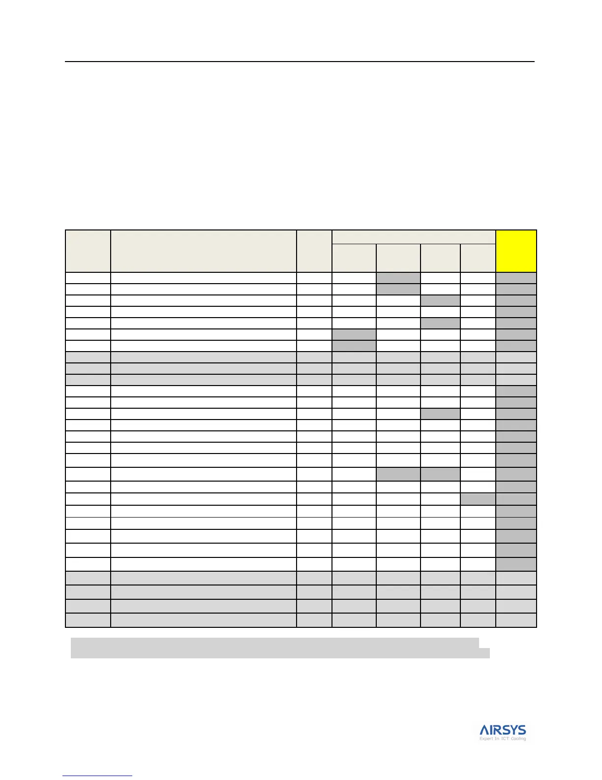
Table 20 lists the alarm codes that may display with a brief description. Table 22 on page 52 provides more detail on
troubleshooting alarms should they occur during operation of the system.
Table 20: Summary of System Alarms
Prime power outage (Only if DC Failover is used)
Indoor temperature sensor defective
Backup indoor temp. sensor defective
Indoor & backup indoor temp. sensors defective
Outdoor temp. sensor defective
HVAC 1 supply air temp. sensor defective
HVAC 2 supply air temp. sensor defective
HVAC1 air flow defective or DC part powered off
HVAC2 air flow defective or DC part powered off
HVAC1 AC part powered off alarm
HVAC2 AC part powered off alarm
1. Alarm codes listed in the table above will result in an audible tone and a red alarm light presented on the PLD.
2. A09, A10&A11 will not display if the HVAC is equipped with DC EC supply fan and ASLLC.2.48 is chosen.
3. A29, A30, A31& A32 will not display if the HVAC is equipped with AC EC supply fan and ASLLC.2 is chosen.
4. HVAC major alarm will not be cleared until manually reset or the components can work normally at the next working time.
5. If a Low pressure or High pressure alarm is triggered 3 times in one hour, the corresponding unit will LOCKOUT. This
means only the supply fan will operatate with no compressor function. There are two ways to clear the alarm: a. Power
cycle the controller or b. Access the parameters in the table: L04-U2L (Manual reset if low pressure) or U2E (Manual
reset if high pressure).