Chapter 4: Preventive Maintenance
Preventive Maintenance Schedule
Page 68
Check Main Voltage
For the main voltage, check:
The main voltage is ranging within ±10% of the rated voltage required by the machine (230V, 60Hz).
The DC voltage is in normal range, if applicable. (36VDC~ 57VDC)
The main electrical supply cable and the terminals, including the user terminal cable, are correctly hooked up.
All cables are secured to the system.
Check Wiring and Components
For wiring and components, perform a preliminary check to verify the system is functional:
Check that the system has been installed correctly.
Check that the wiring cable sections meet current capacity. Report any incorrect mounting and setting to the
AAST who installed the system so that the necessary modifications can be made.
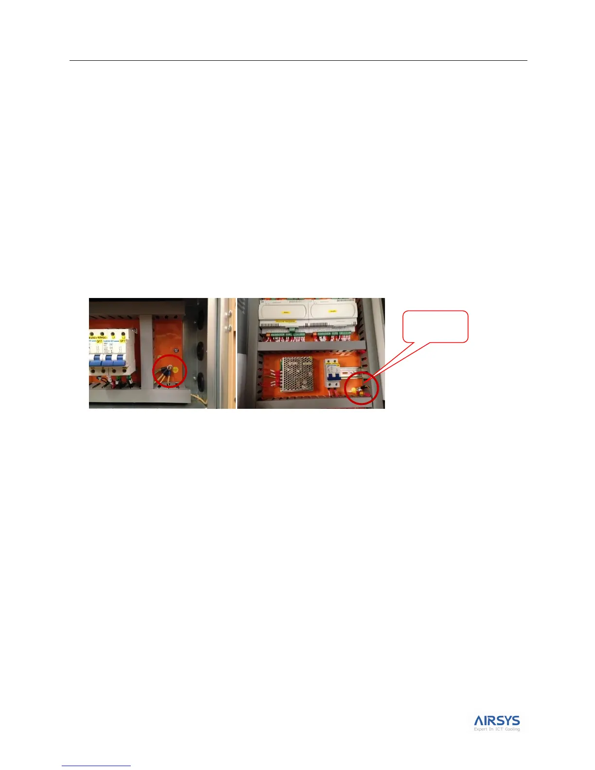
Check that the grounding cables have been installed in the controller box and unit as shown in the graphic.
Perform the Step-Test
The purpose of this test is to simulate real operation without damaging components due to incorrect operation or
protection failures.
Use the step-test to check that the relays, breakers, and components work normally. For details on executing this
test, see “Executing the Step Test”on page 48.
Refer to “Alarms” on page 50 if any alarm occurs during the step test. Refer to wiring diagram included in
the controller shipment for possible mechanical/electrical issues.
Wiring diagram is also available on tempesthvac.com.