Service Manual Aktilite
CL128
Version 1.
3
Page 28
of 41
1.11
Lamp including parallel arm assembly
1.11.1
Fixed lamp head (128
-0-
250)
Required items
Part #
# of items
Description
128
-0-
200
1
Lamp head module
128
-0-
210
1
Parallel arm with lamp head holder unit
128
-1-
216
1
Fricti
on pad
128
-0-
213
1
Spring unit
128
-1-
937
1
Screw
Set screw M
8
x12
128
-1-
942
1
Aluminium washer
128
-1-
916
1
Circlip
128
-1-
211
1
Cover
Lamp head holder unit
128
-1-
936
2
Screw
s
M4x10 countersunk
128
-1-261 1
Re
ceptacle Body (
B
ayonet plug)
128
-1-
136
1
Label Power Plug
128
-1-
956
Loctite 243 glue
Assembly description
Step 1)
Insert the friction pad (128
-1-
216) in the lamp head holder unit of the parallel arm (128
-0-
210).
Step 2)
Slide the vertical axle of the lamp head modul
e (128
-0-
200) into the lamp head holder unit
of the parallel arm (128
-0-
210).
Step 3)
Slide the aluminium washer (128
-1-
942) onto the vertical axle.
Step 4)
Assemble the circlip (128
-1-
916) onto the vertical axle. Make
sure that the circlip is fully engaged in the groove
on the axle.
Step 5)
Insert the spring unit (128
-0-
213) into the lamp head holder
unit of the parallel arm (128
-0-
210).
Step 6)
Assemble the M6x12 set screw (128
-1-
937) into the lamp head
holder unit of the parallel arm (128
-0-
210). Tighten until the
friction in the vert
ical axle is appropriate.
Step 7)
Assemble the cover (128
-1-
211) onto the lamp head holder unit of the parallel arm (128
-0-
210) using the two countersunk M4x10 screws (128
-1-
936).
Step 8)
Pull the power cable (128
-1-
302) from the lamp head module (128
-0-
200) thru the para
llel
arm (128
-0-
210). Leave about 10 cm of slack on the cable between the lamp head module
(128
-0-
200) and the parallel arm (128
-0-210). (So the cable doesn t get stretched at the
extreme positions of the lamp head.)
Step 9)
Put the stain relief onto the DC power
cable. Put on the male crimp pins using the specially
made crimping tool. Put the cord numbered 1 into "D" [+] in the
bayonet
plug, and the pin
with cord marked 2 in "B" [
-
] in the
bayonet
plug. If you make a mistake, you can use the
specially made extract
or tool to release the pins from the
bayonet
plug again.
Step 10)
Put a drop of Loctite 243 on the threads at the strain relieve threads and screw the strain
relief to the
bayonet
plug. Secure the lead with the cross bar and two self threading screws.
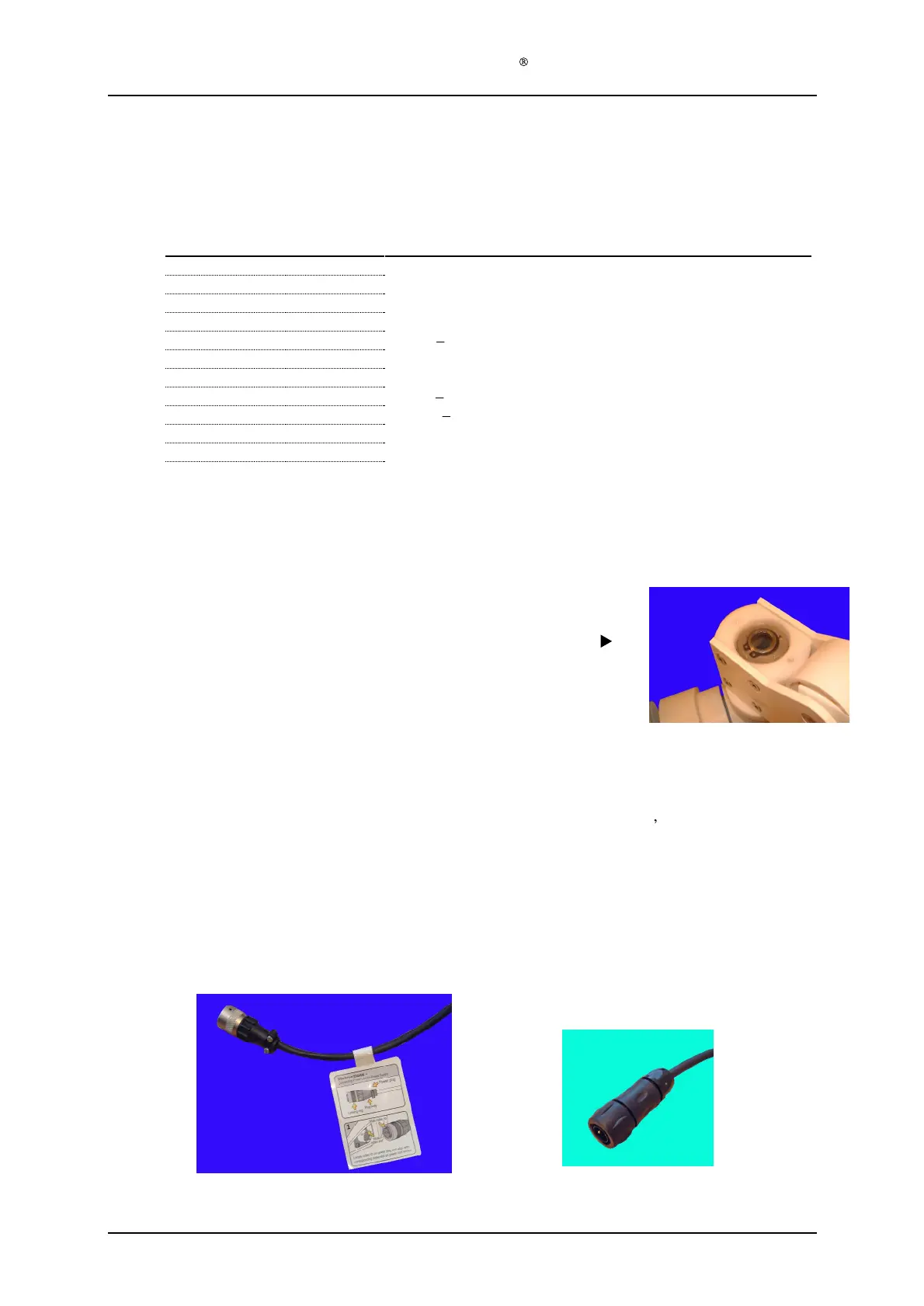
Step 11)
Remove the pr
otective paper from the backside of the Label Power Plug (128
-1-
136) and
attach the label to the cord, next to the
bayonet
plug (see picture below).
NB!
Use new stronger plug
Souriau UTS 6JC104P
for repair
ed lamp
s
, ref Chapter
2