Service Manual Aktilite
CL128
Version 1.
3
Page 38
of 41
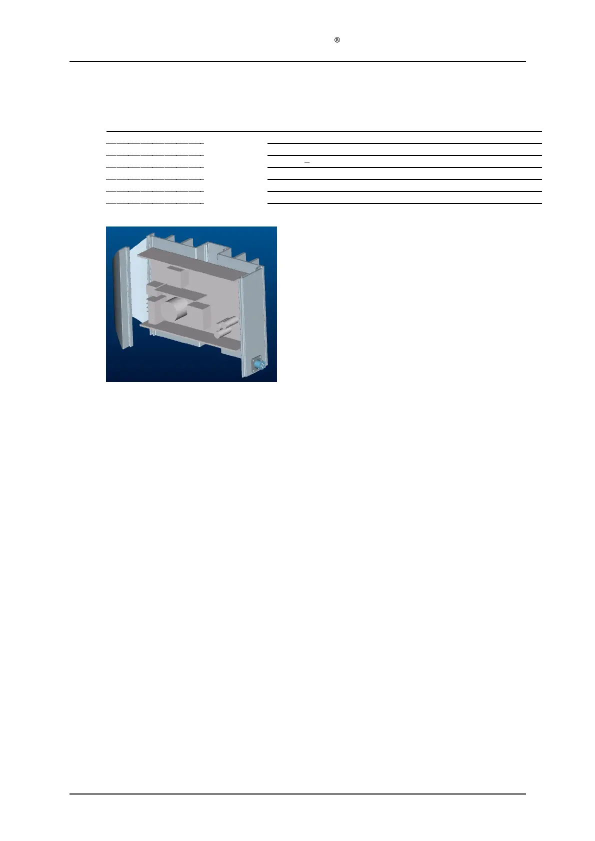
3.4
PS housing module B (128
-0-
320) assembly
Required items
Part #
# of items
Description
128
-1-
321
1
Power supply housing profile, type B
128
-1-
323
1
DC power outlet plug
128
-1-
324
4
Screw
s
PT
3x8
pan head
128
-0-
330
1
Power supply electronics module
128
-1-
322
4
Screw
s
M4x10 countersunk
Tool B, screwdriver Torx
10
Tool C, screwdriver Torx
20
Assembly description
Step 1)
Assemble the DC power outlet plug (128
-1-
32
3) onto the PS housing profile B (128
-1-
321), with the 4 button head PT
-
DG screws (128
-1-
324). Make sure it is fastened in the
correct position, with one of the 3 locking pins facing upwards. Use Tool B.
Step 2)
Remove the paint from two of the 4 holes in the PS h
ousing profile B, for assembling the
PS electronics module, to ensure electric contact between the M4 screw and the PS housing
profile B. Use Tool D.
Step 3)
Assemble the PS electronics module (128
-0-
330) onto the PS housing profile, type B (128
-
1-
321), with the 4
screws (128
-1-
322). Make sure that the red and black load cables are on
the same side of the profile as the power outlet plug. Use the Use Tool C.
Step 4)
Plug the red and black load cables into the correct holes in the power outlet plug. The red
load cable (+) goes into the slot marked D, and the black load cable (
-
) goes into the slot
marked B.