Service Manual Aktilite
CL128
Version 1.
3
Page 27
of 41
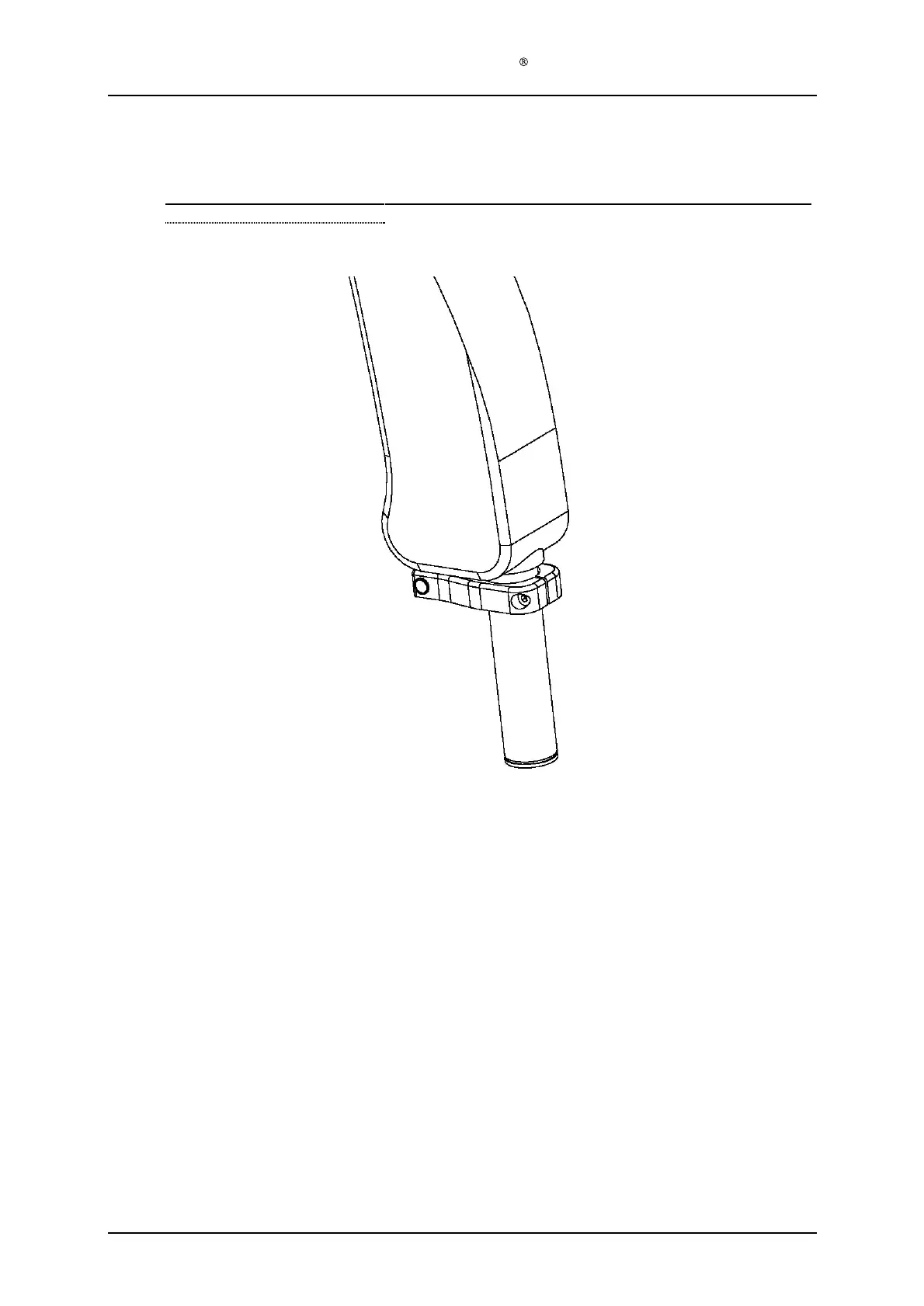
1.10
Stop block module (TS1
-0-
250) assembly
Required items
Part #
# of items
Description
128
-1-
223
1
Parallel arm
TS1
-1-
250
1
Stop block module
Assembly description
Step 1)
Fit the stop block module onto the shaft of the parallel arm.
Assure that the tap on the
stop plate points upwards and engages with the slot on the parallel arm.
Use a
ham
mer and a purpose
-
made cylinder over the shaft to knock the stop block module into
place. The gap between the arm and the stop block module should be as little as possible
and no more than 1 mm.
Step 2)
Secure the stop plate by tightening the S3
Allen
screw to a t
orque of 3.0 Nm using a torque
driver.