Service Manual Aktilite
CL128
Version 1.
3
Page 39
of 41
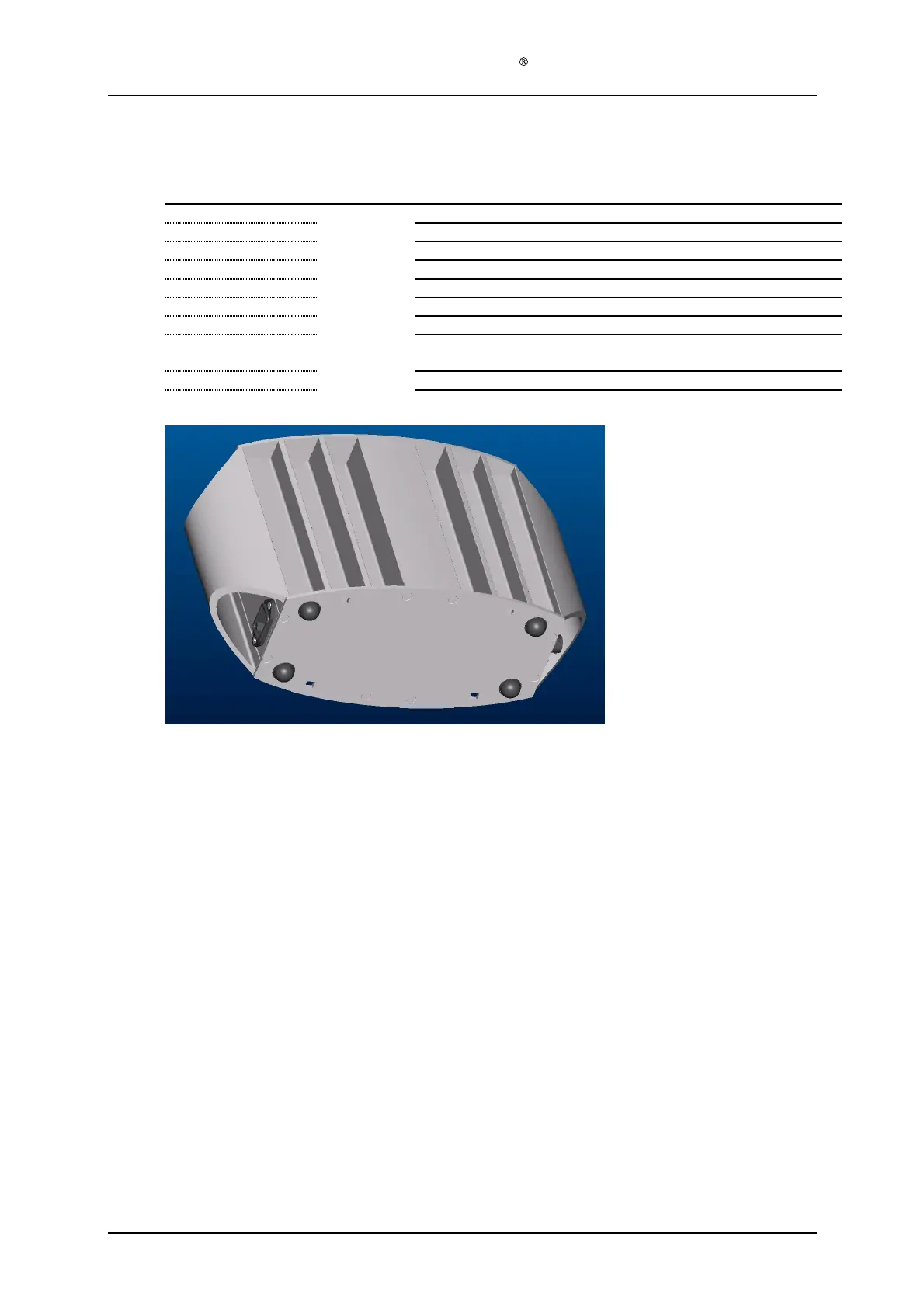
3.5
Power supply (128
-0-
300) assembly
Required items
Part #
# of items
Description
128
-0-
320
1
PS housing module B
128
-0-
310
1
PS housing module A
128
-1-
301
1
PS housing
top cover
128
-1-
302
1
PS housing bottom cover
128
-1-
306
16
Countersunk s
crew
s
4.2x19
128
-1-
307
4
Rubber pad
s
(self adhesive)
128
-1-
309
1
Label on
side wall of power supply
Strip, glue or other suitable means of fixing the ferrite to the PS
electro
nics metal casing.
Tool C screwdriver Torx T20
Tool D, paint removing tool (drill or grinder)
Assembly description
Step 1)
Put the PS housing module B (128
-0-
320) upside down on the table. Slide the PS housing
module A (128
-0-
310) gently into module B.
Make sure that all 4 grooves engage. Make
sure that the three power inlet cables are reachable.
Step 2)
Connect the three AC power inlet cables to the AC power inlet plug. Make sure that the
cables are correctly connected, blue cable to the tongue marked N, brown
cable to the metal
tongue marked L, and the green/yellow cable to the metal tongue marked with the ground
symbol.
Step 3)
See that the voltage can be adjusted to more than 51.2 Volts and then adjust the voltage
down again to 50.4 Volts by means of a thin screwdriv
er according to TCU
-
002
-
128. If the
power supply cannot be adjusted to 51.2 V or more, the power supply should be rejected.
Step 4)
Fix the ferrite to the PS electronics' metal casing with a strip, silicone or other means. There
are two holes in the PS electronics
' metal casing, suitable for this.
Step 5)
Remove the paint from two of the 8 holes in each of the PS housing end covers, to ensure
electric contact between the PT
-
DG screw and the PS housing profiles. Use Tool D
Step 6)
Assemble one PS housing top cover (128
-1-
301) with
the PT
-
DG screws (128
-1-
306).
Make sure that the two housing modules are aligned before inserting the two screws that
engage with both modules. These two screws may be left until the other 6 screws are
tightened. Ensure electric contact between the end cov
ers and one of the housing modules.
Step 7)
Assemble the other power supply end cover (128
-1-
301).