Service Manual Aktilite
CL128
Version 1.
3
Page
7
of
41
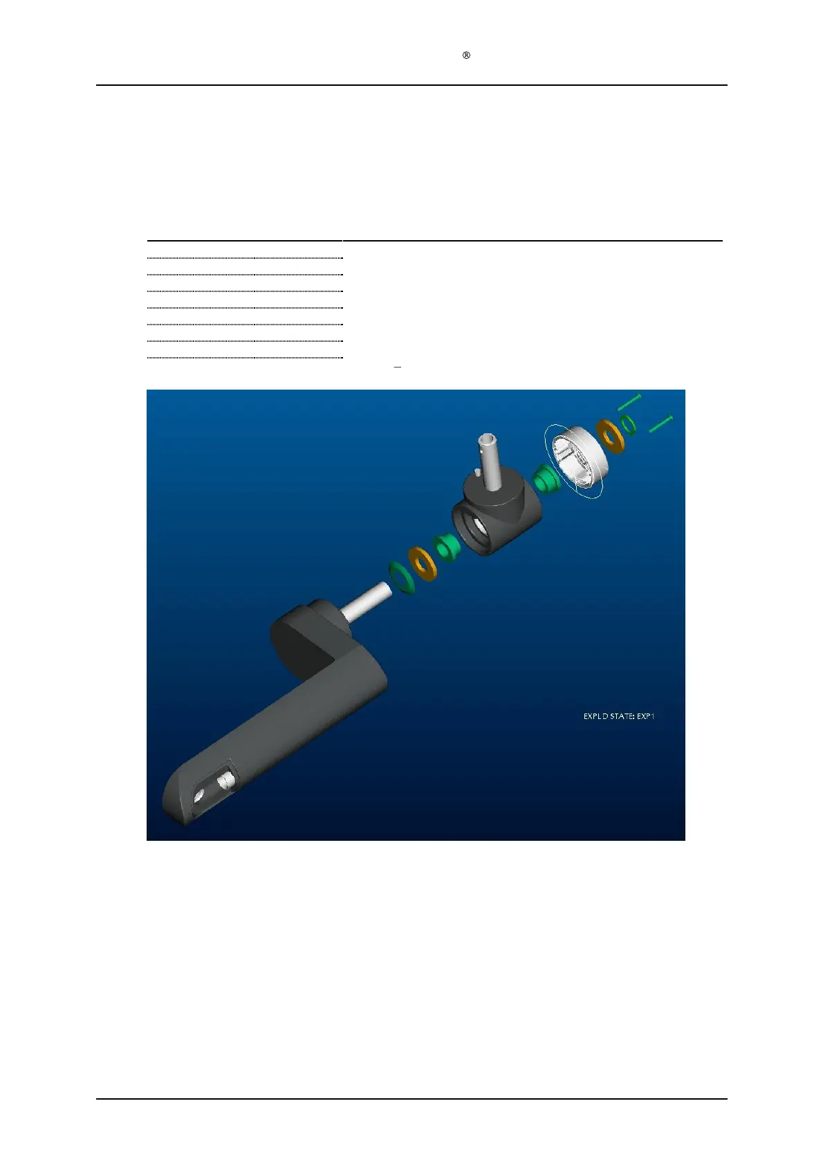
1.6
Positioning arm module (128
-0-
400) assembly
1.6.1
F
ixed lamp head
Required items
Part #
# of items
Description
128
-0-437 1 T-
pi
ece (Moulded plastic)
128
-1-
910
2
Plastic bearing
s
128
-0-
428
1
Main arm (Moulded plastic)
128
-1-
914
2
Aluminium washer
s
128
-1-
912
1
Conical spring
128
-1-
916
1
Circlip
128
-1-
424
1 T-
piece cover (Moulded plastic)
128
-1-
926
2
Screw
s
PT3x25
Assem
bly description
Step 1)
Press the two plastic bearings (128
-1-
910) into the T
-
piece (128
-0-437
). (Specially made
tool is necessary for this or a jig made by Kitron.)
Step 2)
Slide conical spring (128
-1-
912) onto aft tube of the main arm (128
-0-
428), The pointed
end of the
conic spring (128
-1-
912) goes towards the plastic of the main arm (128
-0-
428).
Step 3)
Assemble one aluminium washer (128
-1-
914) and the T
-
piece (128
-0-437
) (Including the
already assembled plastic bearings (128
-1-
910)).
Step 4)
Compress the conical spring (128
-1-
912) by
holding the T
-
piece (128
-1-4
37
) tightly against
the main arm (128
-1-
428). (This compression and holding can be done with one hand.)
Step 5)
Assemble another aluminium washer (128
-1-
914) and circlip (128
-1-
916). Make sure that
the Circlip is well located in the g
roove.
Step 6)
Assemble T
-
piece cover (128
-1-
424) using the two PT3x25 screws (128
-1-
926).