Service Manual Aktilite
CL128
Version 1.
3
Page 32
of 41
1.12.2
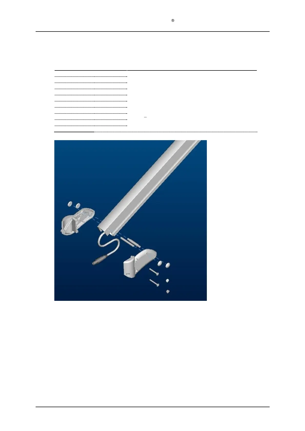
Detachable lamp head (128
-0-
212)
Required Items
Part #
# of items
Description
128
-1-
223
1
Parallel arm
128
-1-
961
1
Lamp head holder outer right
128
-1-962 1
Lamp head holder outer left
128
-1-
968
1
Pinbolt upper
128
-1-
969
1
Pinb
olt lower
128
-1-
965
1
Screw cap for top screw
128
-1-
966
1
Screw cap for bottom screw
128
-1-
967
2
Screw
PT
-
K 40x35
128
-1-
940
4
Starlock Caps BV 6666
-
03C
128
-0-
989
1
Cable from PS unit to lamp head connector
Assembly description
Step 1)
Position the pow
er cable (128
-0-
989) in the parallel arm (128
-1-
223) with the installed male
connector at the lamp head side. The power cable shall be positioned with sufficient slack
(approx. 15cm) on the lamp head side to avoid the cable to get stretched at the extreme
positions of the lamp head.
Step 2)
Install the upper (128
-1-
968) and lower (128
-1-
969) pinbolt in the respective holes in the
parallel
arm
.
Step 3)
Assemble the right (128
-1-
961) and left (
128
-1-
962
) lamp head holder
s
in the pinbolts and
secure the position with the four
starlock
cap
s (128
-1-
940)
. Avoid damage to the starlocks.
Step 4)
Screw the two PT
-
K 40x35 (128
-1-
967) through the holes in the outer right lamp head holder
(128
-1-
961)
.
Step 5)
Assemble the upper (128
-1-
965) and lower (128
-1-
966) screw cap
.