Service Manual Aktilite
CL128
Version 1.
3
Page 30
of 41
Assembly description
Step 1)
Ass
emble chronologically the security pin (128
-1-
977), teflon washer (128
-1-
976) and circlip
(128
-1-
916) onto the T
-
piece
(128
-0-
437)
vertical axle. Make sure that the circlip is fully
engaged in the groove on the axle.
Step 2)
Insert break shoe (128
-1-
964)
and
sprin
g (128
-1-
974) in
both
inner lamp head
holders (128
-1-
959 and 128
-1-
960). The orientation of the break shoe is given by a small recess
in the inner
lamp head holder for the
spring
to
rest again
st
Step 3)
Assemble the inner lamp head holders (128
-1-
959 and 128
-1-
960
) onto the T
-
piece (128
-0-
437)
vertical axle and secure them using the two M5×25 umbraco screws (128
-1-
973) and
corresponding nuts (128
-1-
975)
NOTE:
The parallel arm shall be secured with
the
attached strap to avoid the
parallel arm to
open uncontrolled. There are very strong springs inside the parallel arm that can cause
serious damage when the lamp head is not installed.
Step 4)
Assemble the lamp head module (128
-0-
200) by position the inner lamp head holder to the
outer lamp head holder on the parallel arm (
1
28
-0-
212
). Secure the position by installing the
spring lock washer (128
-1-
972) and the M5×45 umbraco screw (128
-1-
980) through both inner
and outer lamp head holders.
Step 5)
Assemble the top cover (128
-1-
963) onto the lamp head holder by pressing it down in pos
ition.
Note that the cover shall be installed with the knobs located on the inside of the cover at the
lamp head side, i.e. away from the parallel arm.
Step 6)
Put the stain
relief
onto the DC power cable. Put on the male crimp pins using the specially
made crimpi
ng tool. Put the cord numbered 1 into "D" [+] in the bajonet plug, and the pin with
cord marked 2 in "B" [
-
] in the bajonet plug. If you make a mistake, you can use the specially
made extractor tool to release the pins from the bajonet plug again.
Step 7)
Put a dr
op of Locktite 243 (128
-1-
956) on the threads at the strain
relief
and screw the strain
relief
to the bajonet plug.
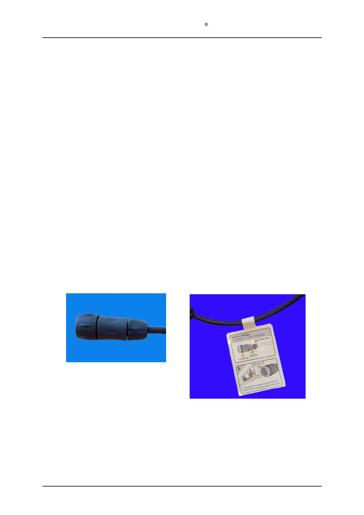
Step 8)
Remove the protective paper from the backside of the Label Power Plug (128
-1-
136) and
attach the label to the cord, next to the bajonet plug
(see picture below).