Functioning
akYtec GmbH · Vahrenwalder Str. 269 A · 30179 Hannover · Germany Tel.: +49 (0) 511 16 59 672-0 · www.akytec.de
4 Functioning
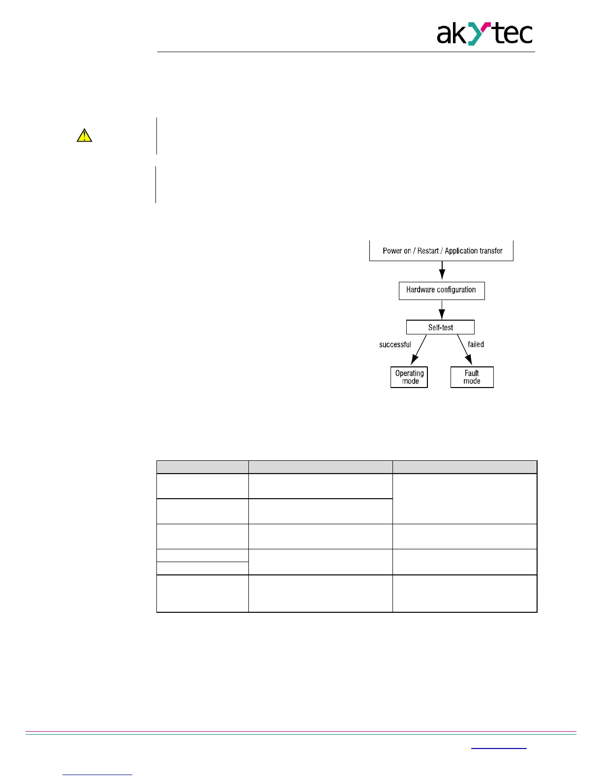
Once the application has been transferred to the non-volatile memory, the relay restarts. On
startup the relay runs a self-test. If unsuccessful, the relay switches to the fault mode (see
4.2). Otherwise the application runs (Fig. 4.1)
Before transferring the application to PR200 ensure that all devices connected to
the relay outputs are disconnected. It is recommended to transfer the application
Before switching on, make sure that the device was stored at the specified ambient
temperature (-20 ... +55 °C) for at least 30 minutes.
4.1 Operating mode
Operating mode of the device is cycle oriented:
− Start (testing of operational readiness)
− Update of the input process image
− Running the application
− Update of the output process image
− Back to Start.
Fig. 4.1 Operating sequence
4.2 Fault mode
Table 4.1 – Error messages
Repare application with ALP
LOGIC Program
MEMORY ERROR
Retain variables cannnot be
read
application stopped (see 4.6)
Remove the RUN-STOP jumper
Update firmware or contact the
Start the application using
system menu and restart the
device
4.3 RS485 network interface
PR200 can have up to two RS485 interface cards (depends on modification) for
communication via Modbus RTU / ASCII protocol as a Master or a Slave.
The interface card PR-IC485 is set to Slave by default. To use the interface as a Master,
jumpers XP4 and XP5 on the card must be set in accordance with the Fig. 4.2:
− set jumpers on the interface card to the ‘M’ position
− configure the interface using the ALP software (Menu>Device>Configuration)