6 Configuration
PR200 has to be configured before use. Configuration is carried out with ALP software and
is transferred as a part of the user application to the device. The configuration parameters
are stored in permanent memory of the relay and are safe if device is powered off. Detailed
information about programming PR200 is given in ALP Help.
Dynamically allocated memory enables to create complicated programs with many functional
blocks, display elements and advanced display management.
6.1 Analog inputs AI1…AI4
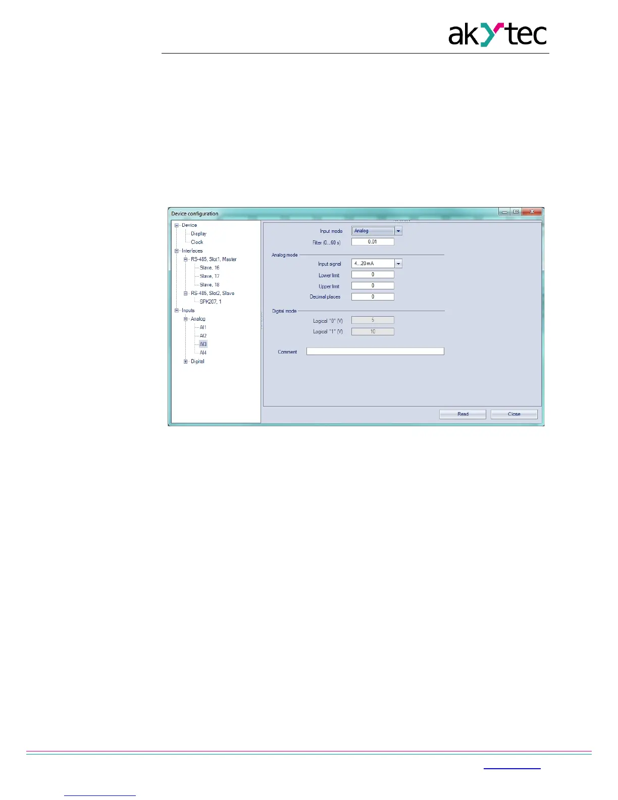
To configure analog inputs use the menu path Device>Configuration. A window ‘Device
configuration’ appears (Fig. 6.1). Select the node Inputs>Analog.
Fig. 6.1 Analog input configuration
For quick access select an input in the circuit program and set the parameters in the
Property Box (see Fig. 6.2). First the parameter ‘Input mode’ has to be set.
Configuration parameters:
Analog input
Input mode – digital or analog mode
Filter – digital input filter time constant (0…60 s)
Analog mode only
Input signal – 4-20 mA, 0-10 V, 0-4000 ohm
Lower limit – lower limit of measured value
Upper limit – upper limit of measured value
Decimal places – ‘dp’ parameter for Modbus request (see Table 4.2)
The parameter ‘dp’ has to be set to determine the accuracy, if the measured value is
transmitted over Modbus as integer.
Digital mode only
Logical 0 – voltage 0…10 V
Logical 1 – voltage 0…10 V