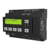
Fig. 6.2 Property Box
6.1.1 Analog mode
While creating an application the type of input signal must be selected. On the hardware side
each input must be configured using jumpers in accordance with the selection.
If input signal do not correspond with hardware configuration, the device can be
damaged. Check the hardware configuration of inputs before connecting them.
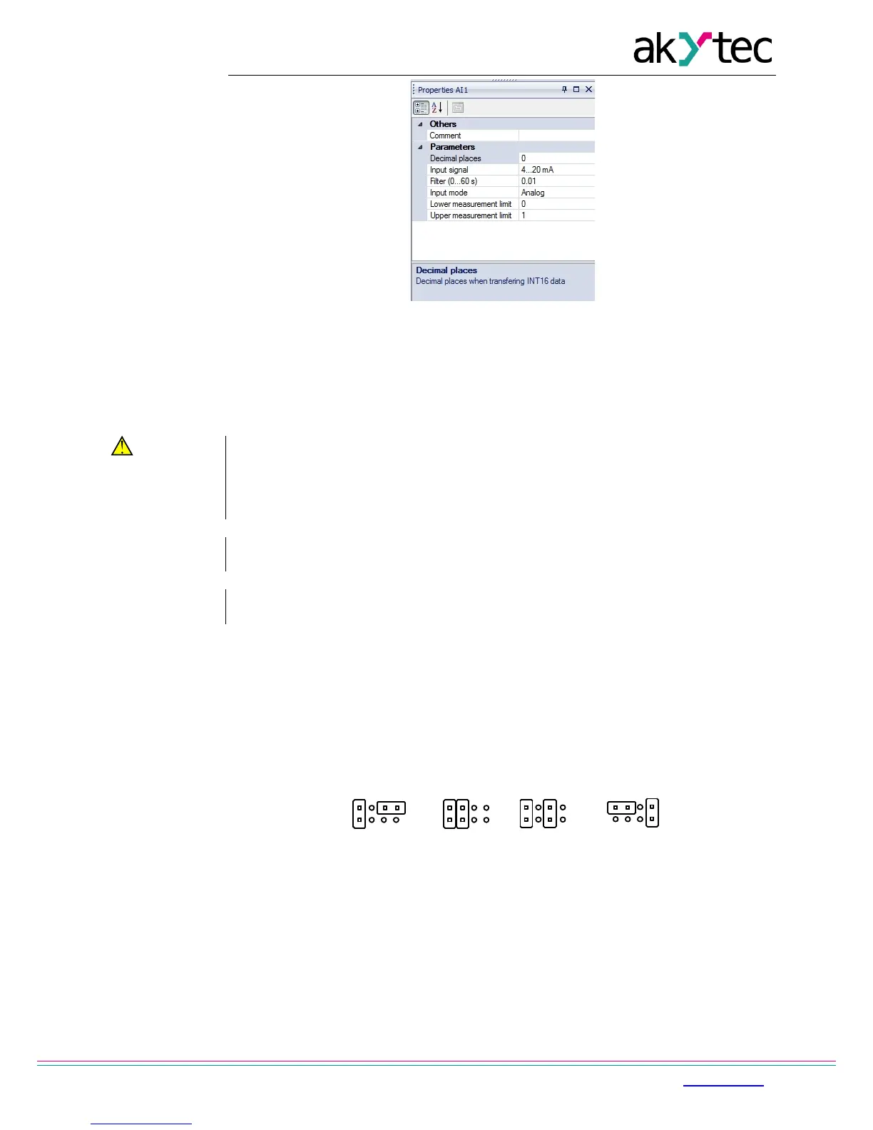
Jumper positions according to input configuration are shown in Fig. 6.3
The location of the jumpers on the board is shown in Fig. 6.4.
To configure the input proceed as follows:
– remove the front housing
– set the jumpers according to Fig. 6.3, 6.4, using a thin tool (e.g. tweezers)
– put the front housing back.
Fig. 6.3 Input configuration jumper positions
a) 0-10 V, b) 4-20 mA, c) digital mode, d) 0-4000 ohm