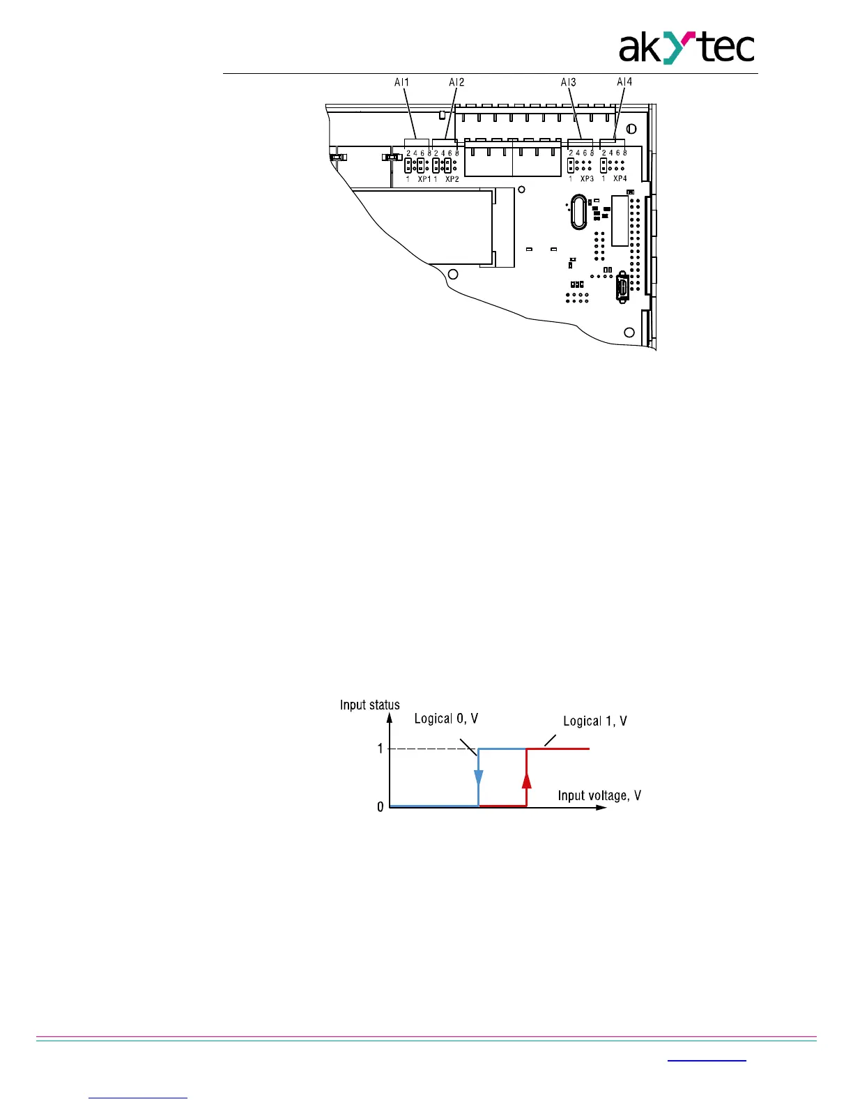
Fig. 6.4 Input configuration jumper location
There is a built-in shunt resistor of 121 ohm for measuring of 4-20 mA input signal in each
channel.
To scale the input signal the lower and upper limit of measured value must be set. Scaling is
not available if the signal 0-4000 ohm is selected. In that case the measured value is
represented only as REAL32.
The parameter ‘Decimal places’ (dp) has to be set to determine the accuracy, if the
measured value is transmitted over Modbus as integer. The parameter is not available if the
signal 0-4000 ohm is selected.
The resistance input is designed for 2 wire sensors. The effect of lead resistance can be
compensated in the application logic.
6.1.2 Digital mode
Input operates as a comparator with parameters Logicall 0 and Logicall 1, which determine
the hysteresis (Fig. 6.5) and can be set in the range of 0…10 V.
Fig. 6.5 Digital mode
6.1.3 Analog input filtering
The input filter is designed to steady the input reading. The input filter setting is a time
constant in milliseconds. It is the time interval within which the signal reaches 0.63 of the
measured value.
The time constant for each input can be set within the range of 0.01…60 s with the
increment of 0.001 second.
The greater the time constant is, the higher the damping of interference signal and the
slower the response to rapid changes of the input value are.