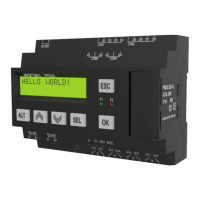
Fig. 4.6 Slave configuration in master mode
To create a variable to be requested click the ‘+’ icon (see Fig. 4.6).
To delete the selected variable click the ‘-’ icon.
Variable properties:
− Name
− Type – data type BOOL, INT16, REAL32
− Register – register address
− Bit – bit number in register (0…15), only for BOOL varables
− Number of registers –variable length
− Read function – Modbus read function
− Write function – Modbus write function
− Start reading – BOOL variable event to start the reading request
− Start writing – BOOL variable event to start the writing request
− Status – INT variable to store the error code
− Comment
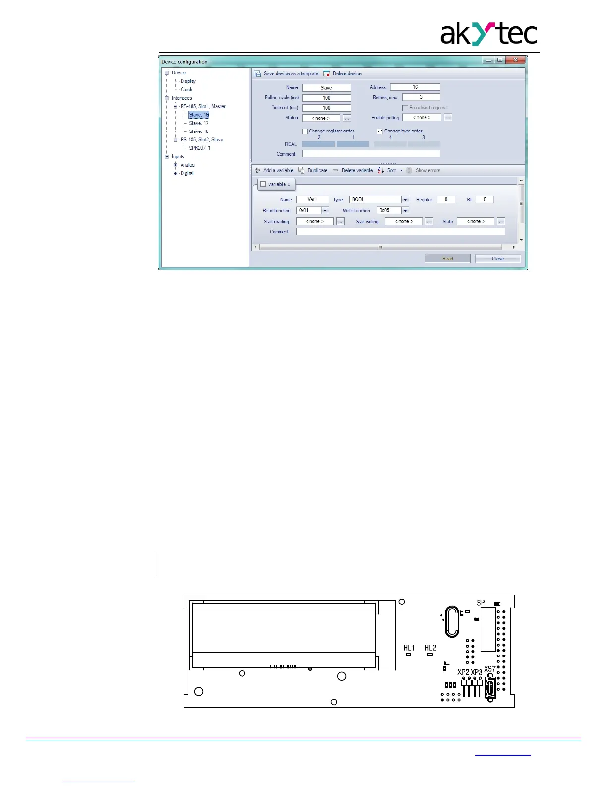
4.6 Special modes
The connectors XP2 and XP3 under the device cover (Fig. 4.5) are used to set special
device modes.