Appendix F. Calibration
akYtec GmbH · Vahrenwalder Str. 269 A · 30179 Hannover · Germany Tel.: +49 (0) 511 16 59 672-0 · www.akytec.de
Appendix F. Calibration
F.1 General
Calibration should be carried out to restore the accuracy of the device
NOTICE
Calibration must be performed only by fully qualified personnel.
– Calibration is performed using the reference signal source connected to the contacts
of the device. During the calibration the ratio between the input signal and the device
reference voltage is calculated.
– The calculated calibration coefficients are stored to non-volatile memory of the
device and used as a base for all calculations.
– Each analog input has its own calibration coefficients for each sensor type.
– If for some reasons the calculated coefficient exceedes the limits, error cause will be
displayed.
F.2 Analog input
Calibration for input signal 4-20 mA, 0-10 V, 0-4000 ohm
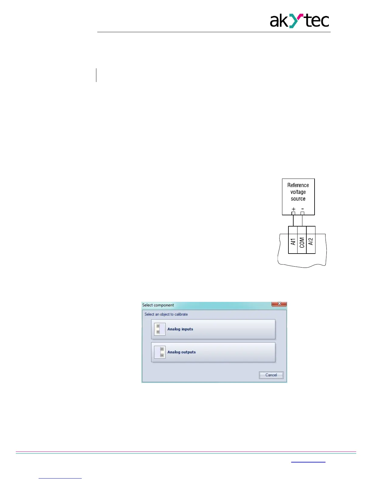
1. Connect the reference voltage source of accuracy class at
least 0.05 to the input AI1 (Fig. F.1).
2. Start ALP software, select menu item Device>Calibration, in
the opened dialogue box select ‘Analog inputs’ (Fig. F.2)
3. Select the input signal.
4. Set the three curve points for calibration, the filter time
constant and select the channel (Fig. F.3). Increasing the filter
time constant increases the time of calibration but provides a
more precise calibration coefficients. Each channel is
calibrated individually. If ‘All channels’ is selected, all four
channels will be calibrated, so it is necessary to select the
appropriate curve points for all channels at once.
5. Click 'Next' to continue and follow the instructions.
Fig. F.1
Fig. F.2