Roles Within the Stack Managing OmniSwitch 6850E Series Stacks
page 6-10 OmniSwitch 6850E Series Hardware Users Guide January 2013
Secondary Management Module Selection
In order to provide effective management module redundancy, all stacked configurations dynamically
assign a backup, or secondary, management module during the boot process. Stacks use two different
methods for selecting the secondary switch. These methods are:
• Stacking connection to the primary switch
• Saved slot number
Using the Stacking Connection to the Primary Switch
By default, the switch that is connected to the primary switch’s stacking port A is automatically assigned
the secondary management role. This applies to stacks on which there is no preassigned slot information—
i.e., there is no boot.slot.cfg file present in any switch.
For more information on using the stacking connection to the primary switch to determine the secondary
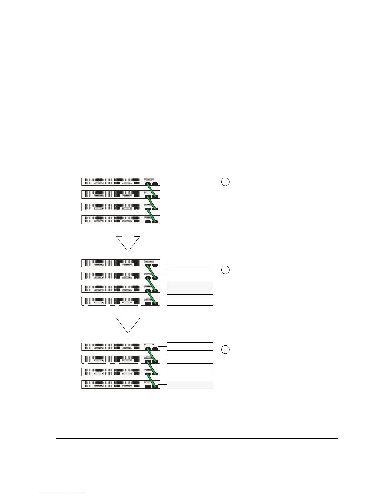
management module, refer to the diagram below:
Secondary Management Module Selection Using the Stacking Connection to the Primary Switch
Note. For information on dynamic slot numbering for idle elements within the stack, refer to “Idle Module
Role” on page 6-12 and “Slot Numbering” on page 6-20.
Four switches are stacked and connected via
stacking cables, as shown. All switches are
currently powered off. None of the switches
have preassigned slot numbers—i.e., there are
no
boot.slot.cfg
files present. The user powers
on all switches in the stack in close succession
and the stack begins the boot process.
By default, the switch connected to the
primary’s stacking port A is automatically
assigned the secondary management role.
The secondary switch is dynamically
assigned slot number 2.
1
2
3
When the elements in the stack come online,
the switch with the lowest MAC address is
given the primary management role and is
dynamically assigned slot number 1.
A B
A B
A B
00:d0:95:b2:3c:8e
00:d0:95:b2:2a:ab
00:d0:95:b2:1c:ff
00:d0:95:b2:5b:8d
Idle
Idle
Primary
Secondary - Slot 2
(Primary - Slot 1)
 Loading...