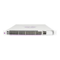
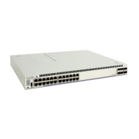
OmniSwitch 6850E Series Chassis and Hardware Components Booting OmniSwitch 6850E Series Switches
OmniSwitch 6850E Series Hardware Users Guide January 2013 page 2-41
Booting OmniSwitch 6850E Series Switches
For information on booting stand-alone switches and switches in stacked configurations, refer to the
sections below.
Booting a Stand-Alone Switch
The OmniSwitch switch does not use an on/off switch. The power cord is the switch’s only connect/
disconnect device. The power connector socket is located on the switch’s rear panel. For more informa-
tion, refer to “Rear Panel” on page 2-55.
To boot the switch, plug the power cord (provided) into the power connector socket at the switch’s rear
panel. Next, plug the power cord into an easily-accessible power source, such as a grounded AC outlet or
an Uninterruptible Power Supply (UPS).
The switch immediately begins the boot process. Allow a few moments for the switch to boot completely,
then verify the status of all LEDs on the switch’s front panel. A successful boot for a stand-alone switch
displays the following LED states:
If any of the LED state differs from the states shown in the table above, refer to page 2-53 for more infor-
mation. Contact Alcatel-Lucent Customer Support if the LED state persists.
For information on logging in and configuring your OmniSwitch, refer to the Getting Started Guide and
Switch Management Guide.
LED States for a Stand-Alone Switch
OK Solid green
Blinking amber - Switch is operational but Auto-Configuration was not
successful.
PRI Solid green
PWR Solid green
BPS Solid amber if BPS attached is failed and off when no operational
backup power supply (BPS) is attached; solid green if an operational
BPS is attached and operating normally.
Slot Indicator 1–8 (non-blinking), depending on the slot number value in the
boot.slot.cfg file. The default value is 1.

 Loading...
