5 WIRING CONNECTIONS
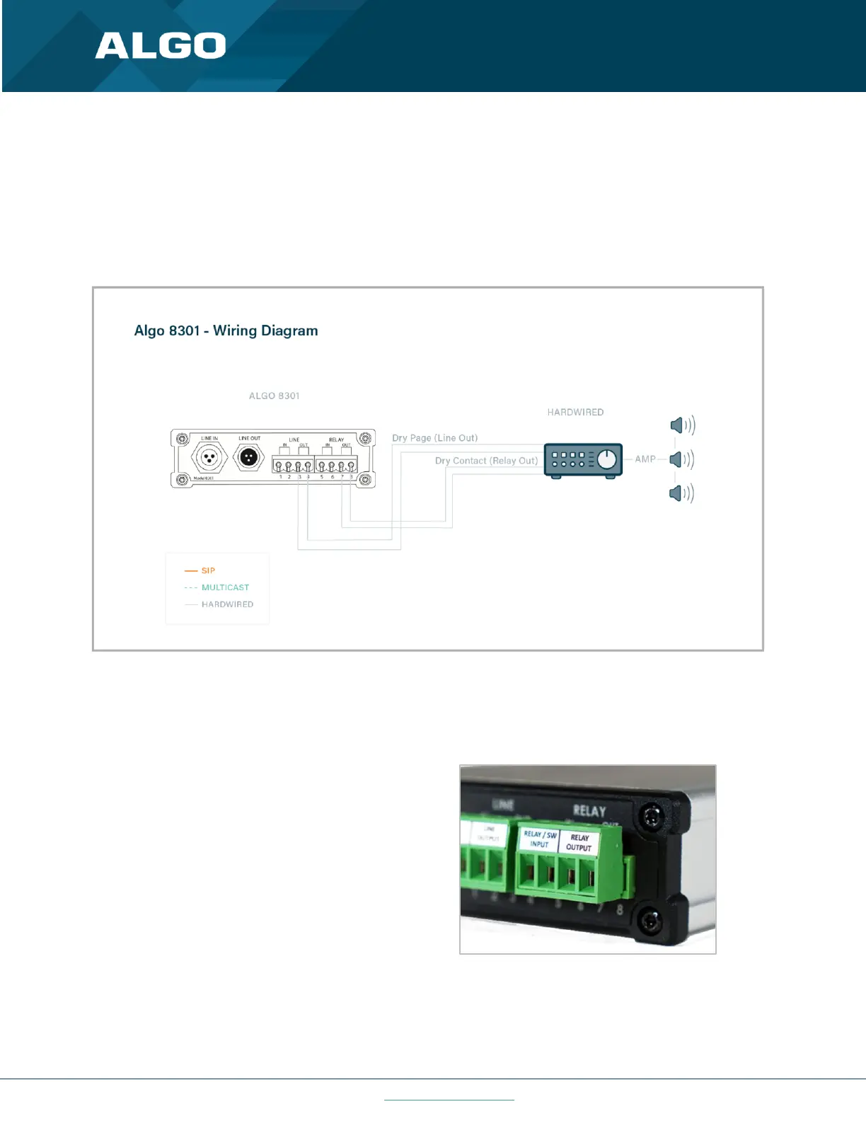
The wiring diagram below illustrates one of the most common use cases, where the Line Output of the 8301 is
connected directly to the dry audio input on an amplifier with an input impedance between 600 Ohm and 10 kOhm.
The output level of the 8301 can be adjusted to match the amplifier’s input specification. Check the Basic Settings →
Features section for more details. The optional dry contact closure can be used to activate the amplifier (if required).
Figure 4: Use Case Wiring Diagram
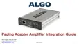
5.1 Connecting Input Devices to 8301
The relay input of the Algo 8301 IP Paging Adapter &
Scheduler can be activated by any normally open or
normally closed switch, or one of several Algo input
buttons/interfaces (e.g. ,1202 Call Button, 1203 Call
Switch, 1204 Volume Control Switch or 1205 Audio
Interface). The input switches can be connected to the
back of the 8301 via the included Terminal Block on
the ‘Relay Input’ pair. To configure the Relay Input
Mode, check the Additional Features → Input/Output
section.