55
2) VCO and RX Adjustment Specification
Adjustment
Frequency
439.00MHz
TX
MAIN TC101 Adjust so that Tx Frequency
becomes within 439.00MHz±100Hz
VCO
Adjustment
425.00MHz
RX
VCO L503 Adjust so that PD voltage becomes
1.7V
VCO
Confirmation
511.95MHz
RX
VCO Confirm if PD voltage becomes less
than 9.0 V
Rx Signal
Sensitivity
Adjustment
440.05MHz
430.05MHz
440.05MHz
450.05MHz
MAIN TC103
TC102
L103, L102
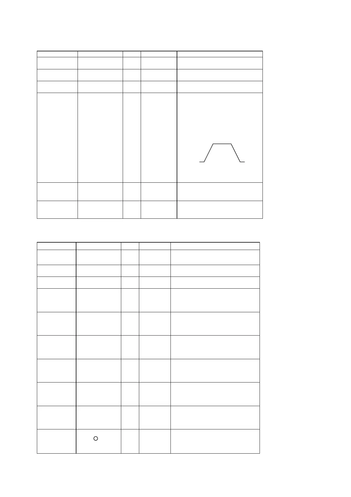
It is a tracking generator from an
antenna connector. -30dBm is
inputted.And when CN109 is seen
with a spectrum analyzer, by the
maximum gain, it becomes as it is
shown in the following figure, and
appearance adjustment is carried
out.
430.00M 450.00M
At -7.5dBu SINAD more than 12dB
At -7.5dBu SINAD more than 12dB
At -7.5dBu SINAD more than 12dB
Squelch
Adjustment
440.05MHz
SSG OFF
Indication 01
MAIN VR101 Adjust so that the squelch stops at
perfectly close location
S Meter
Adjustment
440.05MHz
SSG20dBu 1KHz
3.5KHz/DEV
MAIN VR102 Adjust so that all the indicator
appears
ITEM CONDITION UNIT
ADJ.SPOT
ADJUSTING METHOD
3) Tx Adjustment Specification
HI POWER
Adjustment
440.00MHz
HI POWER
MAIN VR103 Adjust to 35.0±1.0W
MID POWER
Adjustment
440.00MHz
MID POWER
MAIN VR104 Adjust to 10.0±1.0W
LOW POWER
Confirmation
440.00MHz
LOW POWER
MAIN Confirm if it becomes
5.0±1.0W
Maximum
Deviation
Adjustment
440.00MHz
MOD
1KHz40mVemf
WIDE
MAIN VR107 4.5±0.1KHz/DEV
Maximum
Deviation
Adjustment
440.00MHz
MOD
1KHz40mVemf
NARROW
MAIN VR105 2.2±0.1KHz/DEV
Mic Gain
Adjustment
440.00MHz
MOD
1KHz4mVemf
WIDE
MAIN VR106 3.0±0.1KHz/DEV
CTCSS
Modulation
Level
Confirmation
440.00MHz
88.5Hz
MAIN 800±200Hz/DEV 3KHz LPF ON
DCS
Modulation
Level
Confirmation
440.00MHz
255 Code
MAIN 800±200Hz/DEV 3KHz LPF ON
1750Hz
Modulation
Level
Confirmation
440.00MHz
1750Hz
MAIN 3.0±0.5KHz/DEV
DTMF
Modulation
Level
Confirmation
440.00MHz
DTMF
Press the V/M
key during TX
MAIN
ITEM CONDITION UNIT
ADJ.SPOT
ADJUSTING METHOD
3.0 ±0.5KHz/DEV
1