Installation/Wiring
2-20
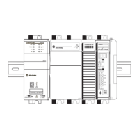
Figure 2.9 TB2 Designations
[Input Mode] = “3 Wire/MOP”
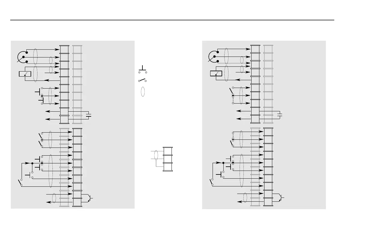
Figure 2.10 TB2 Designations – Two Wire Control Operation
[Input Mode] = “Run F/R MOP”
Remote Pot
1
2
3
4
5
6
7
8
9
10
Source
Wiper or 0-10V DC Input
Common
4-20mA Input
0-10V Output
0-10V
Common
Stop
➂
Start
➂
Output #1
➄
➀➃
➀
24VDC Source
(User Supplied)
11
12
13
14
15
16
17
18
19
20
Enable
➂
Common
Reverse
➂
Jog
➂
Common
MOP Decrement
➂➅
Frequency Source
➂➅
MOP Increment
➂➅
(Sink)
Output #2
User Side
Momentary Input
Maintained Input
Wires must be shielded
Common
Shield
(connect to drive at TB2 Only)
Remote Pot
Run Forward
Run Reverse
Jumper
➀➁
Jumper
➀➃
1
2
3
4
5
6
7
8
9
10
Source
Wiper or 0-10V DC Input
Common
4-20mA Input
0-10V Output
0-10V
Common
Stop
➂
User Side
Start
➂
Output #1
24VDC Source
(User Supplied)
11
12
13
14
15
16
17
18
19
20
Enable
➂
Common
Reverse
➂
Jog
➂
Common
MOP Decrement
➂➅
Frequency Source
➂➅
MOP Increment
➂➅
(Sink)
Output #2
See Table 2.F and
Notes on page 2-21
efesotomasyon.com - Allen Bradley,Rockwell,plc,servo,drive
 Loading...