154 Rockwell Automation Publication 5000-UM005B-EN-P - November 2015
Appendix B Module Tag Definitions
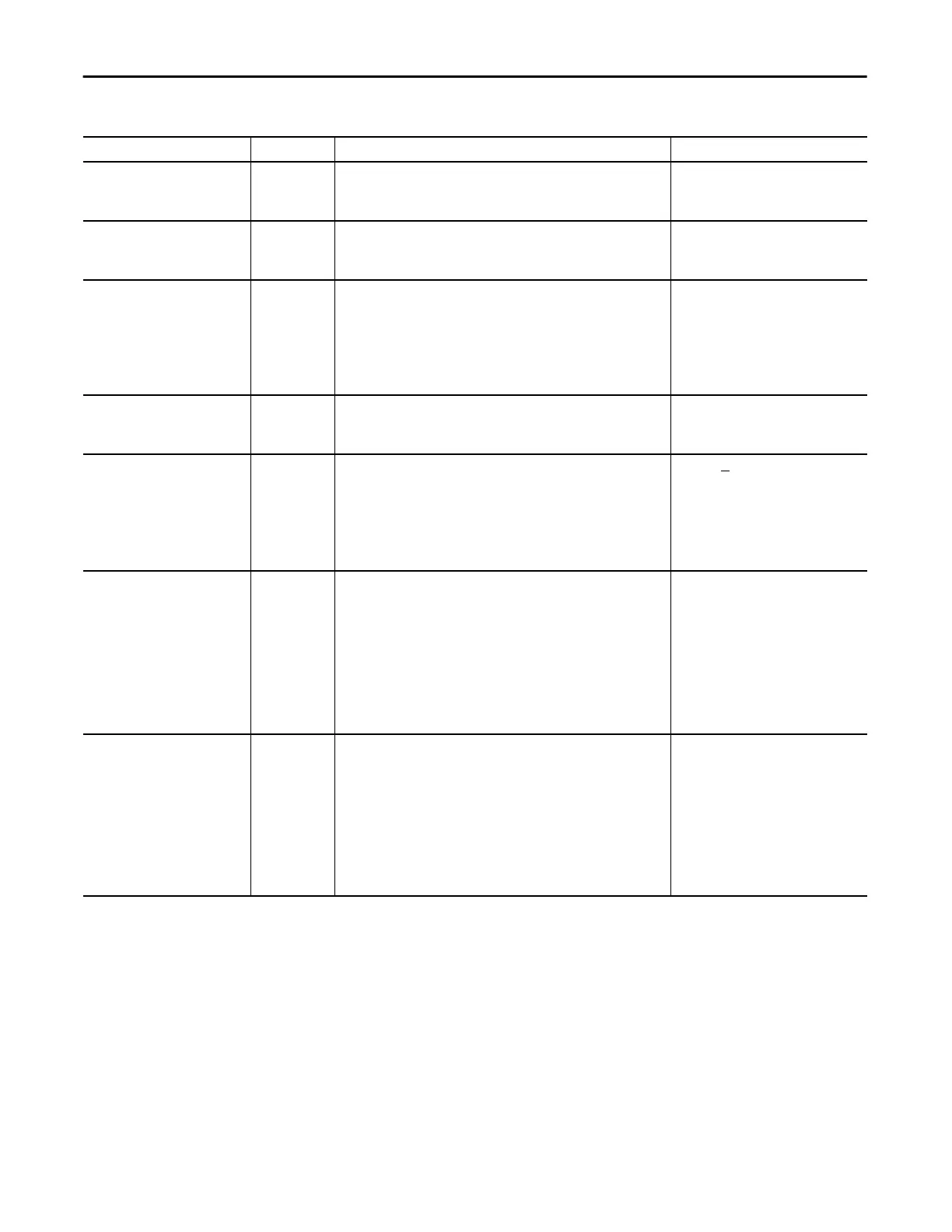
Chxx.RampToProg BOOL Enables Output Ramping when the controller transitions to Program mode.
Output changes during Program mode are limited to the Maximum Ramp
Rate value.
• 0 = Ramping disabled (default)
• 1 = Ramping enabled to Program
mode state
Chxx.RampToFault BOOL Enables Output Ramping when the connection to the module faults.
Output transitions to FaultValue and FaultFinalState are limited to the
MaximumRampRate.
• 0 = Ramping disabled (default)
• 1 = Ramping enabled to Fault mode
state
Chxx.HoldForInit BOOL When set, configures the channel to hold, or not change, until initialized
with a value within 0.1% of full scale of its current value when one of the
following conditions occurs.
• Module initial connection (power up)
• Controller transition from Program mode back to Run mode
• Module reestablishes communication after a fault
• SA power is restored after being lost.
• 0= Output O.Chxx.Data signal
immediately
• 1= Hold last signal until initialization
match
Chxx.FaultValueStateDuration SINT Determines the length of time the FaultMode or FaultValue parameter value
is held prior to the Final Fault State.
• 0 = Hold forever (default)
• Any of the following:
– 1, 2, 5, or 10 seconds
Chxx.MaxRampRate REAL Maximum rate at which the channel can transition to in Engineering Units/
Second.
This tag is used only if at least one of the following output ramping modes
is enabled:
• Ramp In Run
• Ramp To Fault
• Ramp To Program
Any value
> 0.0
1,000,000.00 = default
If the MaxRampRate = 0.0, the ramp rate
is limited to ramping the range full scale in
one RPI.
Chxx.LowSignal REAL One of four points used in scaling. The low signal is in terms of the inputs
signal units and corresponds to the low engineering term when scaled.
Current applications - Any value less than
the high signal in range.
• 0 = default for 0…20 mA range
• 4 = default for 4…20 mA
Voltage applications - Any value less than
the high signal in range.
• -10 = default for -10…10V range
• 0 = default for 0…5V and 0…10V
range
Chxx.HighSignal REAL One of four points used in scaling. The high signal is in terms of the inputs
signal units and corresponds to the high engineering term when scaled.
Current applications - Any value greater
than the low signal in range.
• 20 = default for either current input
range
Voltage applications - Any value greater
than the low signal in range.
• 10 = default for 0…10V and
-10…10V ranges
• 5 = default for 0…5V range
Table 36 - 5069-OF4, 5069-OF8 Module - Configuration Tags
Name Size Definition Valid Values

 Loading...
