342 Rockwell Automation Publication 2198-UM002G-EN-P - February 2019
Appendix A Interconnect Diagrams
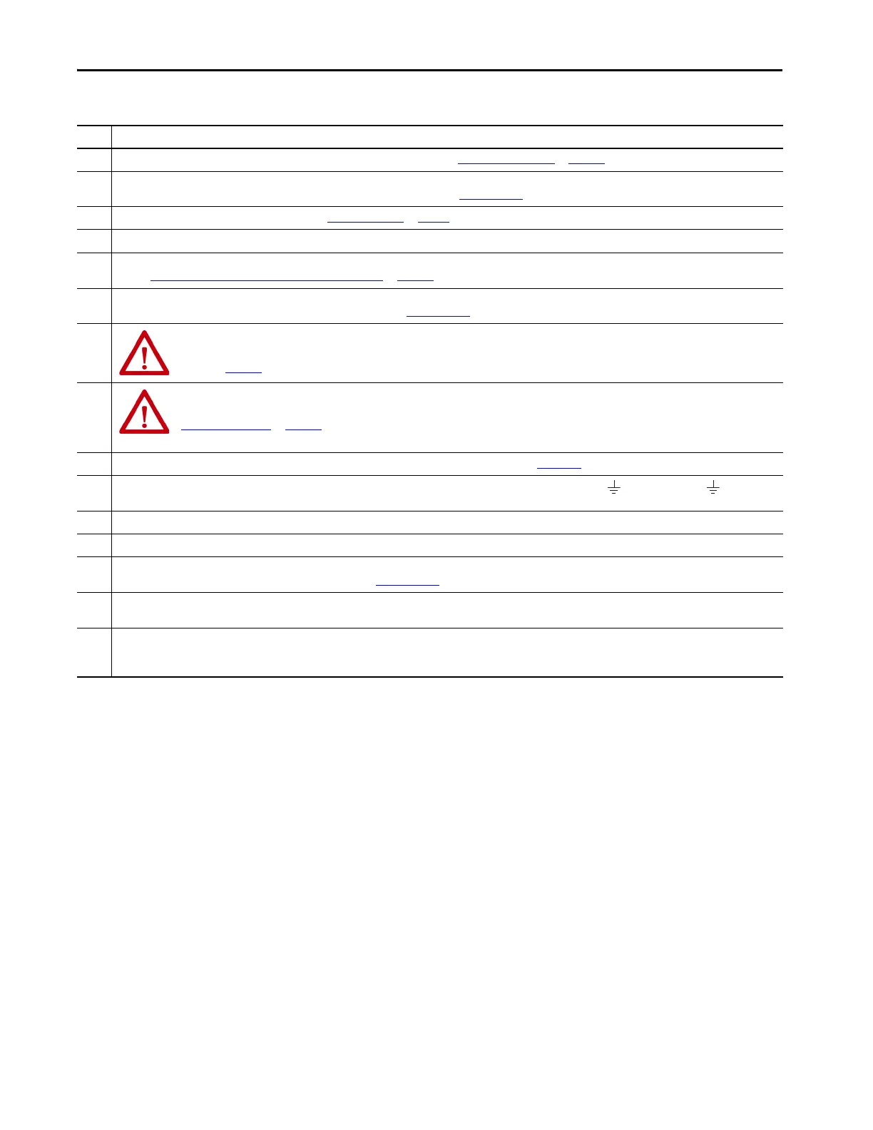
11 PE ground connection bonded to the panel must be used to meet CE requirements. See Ground the Drive System on page 139.
12 Contactor coil (MC) needs integrated surge suppressors for AC coil operation and must have a normally-open auxiliary contact that is terminated at TB3 (24V DC to MC
input as shown). See the 8720MC Regenerative Power Supply User Manual, publication 8720MC-RM001
for contactor types and wiring examples.
13 For M1 contactor selection and specifications, refer to Contactor Selection on page 50.
14 Internal shunt wired to the RC connector is default configuration. Remove internal shunt wires to attach external shunt wires.
15 Default configuration for ground screws or jumper is for grounded power at customer site. For impedance-grounded power configurations, remove the screws/jumper.
Refer to Input Power Configurations for Kinetix 5700 Power Supplies on page 129 for more information.
16 Leave jumper between PR2 and PR3 as shown to use the internal precharge resistor. Remove jumper when external precharge/circuit is required. For more information,
refer to the 8720MC Regenerative Power Supply User Manual, publication 8720MC-RM001
.
17
ATTENTION: Implementation of control circuits and risk assessment is the responsibility of the machine builder. Reference international standards
EN 1050 and EN ISO 13849-1 estimation and safety performance categories. For more information, refer to Understanding the Machinery Directive,
publication SHB-900
.
18
ATTENTION: An AC three-phase mains contactor must be wired in series between the branch circuit protection and the Kinetix 5700 system power
supply. In addition, the AC three-phase contactor control string must be wired in series with the contactor-enable relay at the CED connector. Refer to
Contactor Enable Relay
on page 110, for more information. The recommended minimum wire size for wiring the circuitry to the contactor-enable
connector is 1.5 mm
2
(16 AWG).
19 For motor cable specifications, refer to Kinetix Motion Accessories Specifications Technical Data, publication KNX-TD004.
20 Brake connector pins are labeled plus (+) and minus (-) or F and G respectively. Power connector pins are labeled U, V, W, and (GND) or A, B, C, and (D)
respectively.
21 LDAT-Series linear thrusters do not have a brake option, so only the 2090-CPWM7DF-xxAAxx or 2090-CPWM7DF-xxAFxx motor power cables apply.
22 MPAS-Bxxxxx-VxxSxA (ballscrew) linear stages use the 9V supply. MPAS-Bxxxxx-ALMx2C (direct-drive) linear stages use the 5V supply.
23 Mount the 8720MC-RPS unit on the same panel and as close to the Kinetix 5700 drive system as possible. DC-bus cables not to exceed 2.0 m (6.5 ft), maximum length. See
the 8720MC Regenerative Power Supply User Manual, publication 8720MC-RM001
, for installation and wiring instructions.
24 The 2198-CAPMOD-2240 capacitor module is used in applications with up to 104 A maximum external DC-bus current. You can add the 2198-DCBUSCOND-RP312 DC-bus
conditioner module to the left or right of the capacitor module when the external DC-bus current exceeds 104 A, up to a maximum of 208 A.
25 The Converter OK relay provides a 24V signal to non-Kinetix 5700 inverters indicating that they can draw power from the regenerative power supply and that the power
supply is not faulted. This signal is intended for use with Kinetix 6000, Kinetix 6200, or Kinetix 7000 drives when migrating from the 8720MC-RPS to the 2198-RPxxx
regenerative bus supply. Interposing relay can be required if more than one drive is attached.
Table 170 - Interconnect Diagram Notes (continued)
Note Information
 Loading...


