382 Rockwell Automation Publication 2198-UM002G-EN-P - February 2019
Appendix B Upgrade the Drive Firmware
Before You Begin
The firmware revision for software must be as shown for EtherNet/IP™
networks.
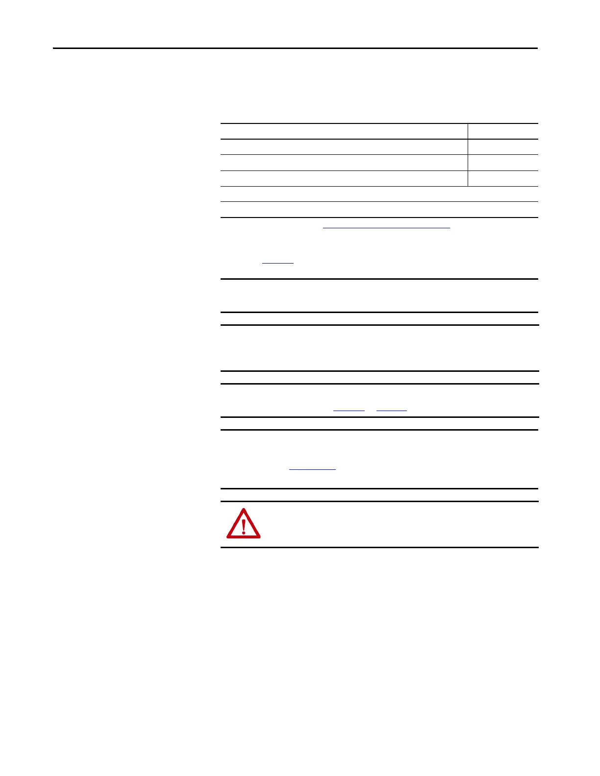
Table 172 - Kinetix 5700 System Requirements
Description Firmware Revision
Logix Designer application 26.00.00 or later
RSLinx® software 3.60.00 or later
ControlFLASH software kit
(1)
(1) Download the ControlFLASH kit from http://support.rockwellautomation.com/controlflash. Contact Rockwell Automation®
Technical Support at (440) 646-5800 for assistance.
For more ControlFLASH information (not drive specific), refer to the ControlFLASH Firmware Upgrade Software User Manual,
publication 1756-UM105
.
12.01.00 or later
Catalog numbers of the targeted Kinetix 5700 drive module you want to upgrade.
Network path to the targeted Kinetix 5700 drive module you want to upgrade.
IMPORTANT Control power must be present at CP-1 (24V+) and CP-2 (24V-) prior to
upgrading your target module.
IMPORTANT For the DC-bus power supply and inverter modules, the axis state on the LCD
display must be STANDBY, CONFIGURING, or PRECHARGE before beginning
this procedure.
IMPORTANT The axis state on the LCD display must be STANDBY, when Protected mode is
enabled. See Table 105
on page 193 for more information.
IMPORTANT For the iTRAK® power supply, the axis state on the LCD display must be in
the START INHIBITED state. See the iTRAK System User Manual, publication
2198T-UM001
for information on upgrading firmware on other iTRAK
system components.
ATTENTION: To avoid personal injury or damage to equipment during the
firmware upgrade due to unpredictable motor activity, do not apply three-
phase AC or common-bus DC input power to the drive.
 Loading...


