Rockwell Automation Publication 2198-UM002G-EN-P - February 2019 107
Connector Data and Feature Descriptions Chapter 4
Universal Feedback Connector Pinouts
These connector pinouts apply to the single-axis and dual-axis inverter.
Table 43 - Stegmann Hiperface and TTL Sine/Cosine Universal Feedback Connector
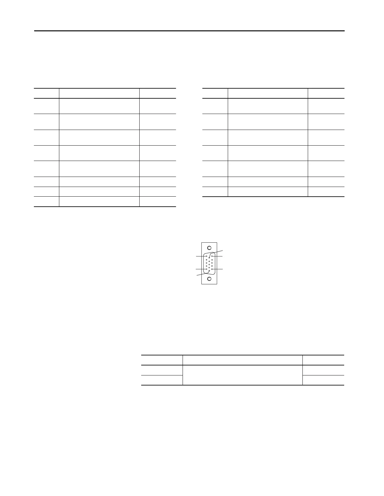
Figure 64 - Pin Orientation for 15-pin Universal Feedback (UFB) Connector
Accessory Module Pinouts
The module status (MS) connector applies to capacitor modules and DC-bus
conditioner modules.
Table 44 - Module Status Connector
UFB Pin Description Signal UFB Pin Description Signal
1
Sine differential input +
A differential input +
MTR_SIN+
MTR_AM+
9 Clock output + MTR_CLK+
2
Sine differential input–
A differential input–
MTR_SIN–
MTR_AM–
10
Data differential input/output –
Index differential input –
MTR_DATA-
MTR_IM–
3
Cosine differential input +
B differential input +
MTR_COS+
MTR_BM+
11 Motor thermostat (normally closed)
(2)
MTR_TS
4
Cosine differential input –
B differential input –
MTR_COS–
MTR_BM–
12 Hall commutation S1 input MTR_S1
5
Data differential input/output +
Index differential input +
MTR_DATA+
MTR_IM+
13 Hall commutation S2 input MTR_S2
6 Encoder common MTR_ECOM 14 Encoder 5V power output MTR_EPWR5V
(1)
7 Encoder 9V power output MTR_EPWR9V
(1)
15 Clock output – MTR_CLK–
8 Hall commutation S3 input MTR_S3
(1) Determine which power supply your encoder requires and connect to only the specified supply. Do not make connections to both supplies.
(2) Not applicable unless motor has integrated thermal protection.
Pin 11
Pin 6
Pin 15
Pin 1
Pin 10
Pin 5
MS Pin Description Signal
1
Module status output
MS
2MS
 Loading...


