Rockwell Automation Publication 2198-UM002G-EN-P - February 2019 341
Appendix A
Interconnect Diagrams
This appendix provides wiring examples and system block diagrams for your
Kinetix® 5700 system components.
Interconnect Diagram Notes
This appendix provides wiring examples to assist you in wiring the
Kinetix 5700 drive system. These notes apply to the wiring examples on the
following pages.
Topic Page
Interconnect Diagram Notes 341
Power Wiring Examples 343
Capacitor Module Status Wiring Example 357
DC-bus Conditioner Module Status Wiring Example 357
Contactor Wiring Examples 358
Passive Shunt Wiring Examples 359
Active Shunt Wiring Examples 360
Kinetix 5700 Servo Drive and Rotary Motor Wiring Examples 362
Kinetix 5700 Servo Drive and Linear Actuator Wiring Examples 367
System Block Diagrams 373
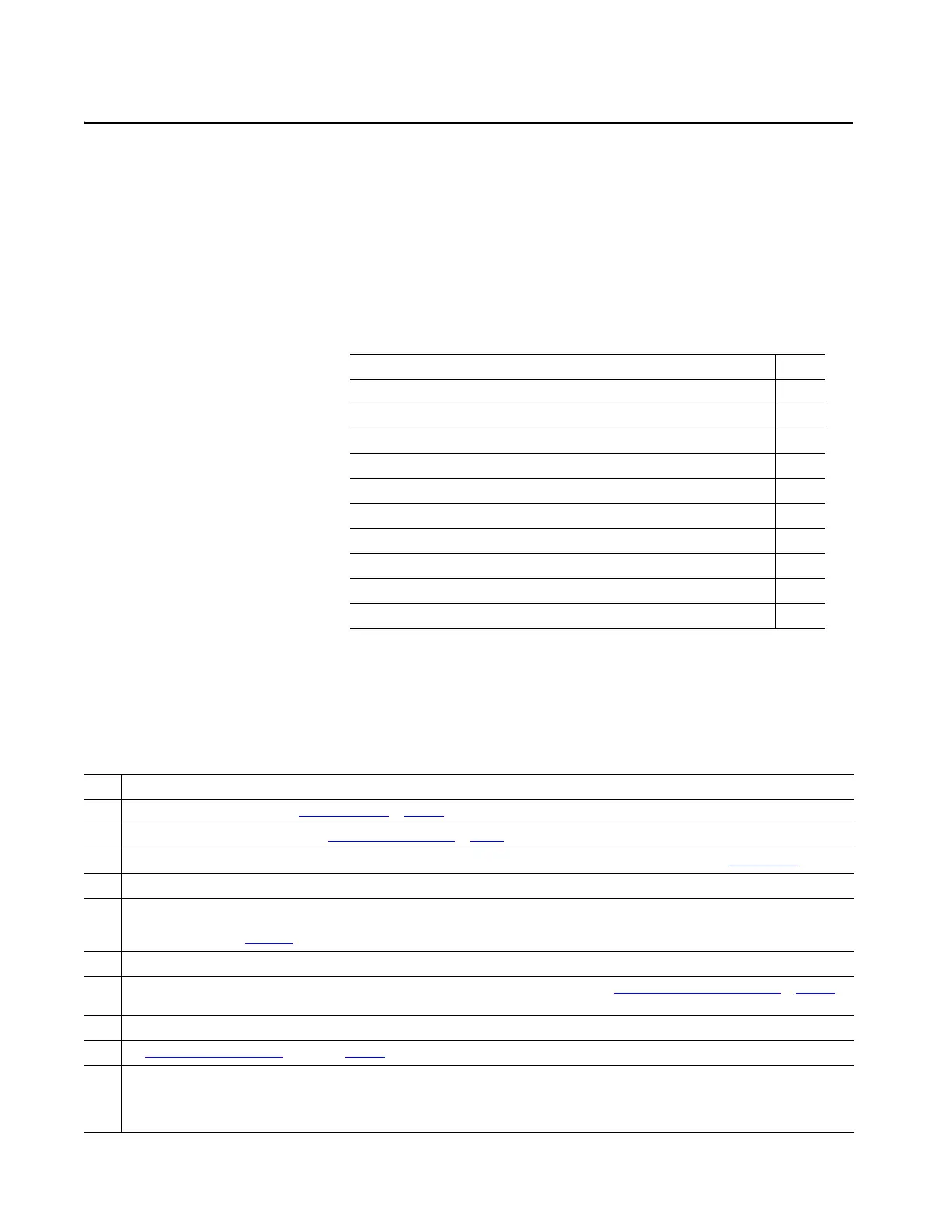
Table 170 - Interconnect Diagram Notes
Note Information
1 For power wiring specifications, refer to Wiring Requirements
on page 141.
2 For input fuse and circuit breaker sizes, refer to Circuit Breaker/Fuse Selection
on page 48.
3 For fuse and circuit breaker sizes and other 8720MC-RPS specifications, see the 8720MC Regenerative Power Supply User Manual, publication 8720MC-RM001.
4 The iTRAK® power supply must have three-phase power sourced from grounded-wye power distribution.
5 AC (EMC) line filter is required for CE compliance. Place line filter as close to the drive as possible and do not route very dirty wires in wireway. If routing in wireway is
unavoidable, use shielded cable with shields grounded to the drive chassis and filter case. For AC line filter specifications, refer to Kinetix Servo Drives Specifications
Technical Data, publication KNX-TD003
. 2198-DBRxx-F line filters are preferred.
6 Terminal block is required to make connections.
7 Cable shield clamp must be used to meet CE requirements with Bulletin 2090 power cables 2 AWG and smaller. See Customer-supplied Motor Power Cables
on page 178 to
meet CE when wiring 2198-S263-ERSx and 2198-S312-ERSx drives with power cables larger than 2 AWG.
8 2198-Dxxx -ERSx dual-axis inverters include separate digital inputs, DSL feedback, universal feedback, motor power, and motor brake wiring plugs for each axis.
9See Digital Inputs Connector Pinouts
beginning on page 103 for digital input configurable functions and default settings.
10 • When a 2198-Sxxx-ERSx single-axis inverter is the first drive module (adjacent to the 2198-CAPMOD-2240 capacitor module) you must configure the Digital Input
category in the Logix Designer application as Regeneration OK and wire the IOD connector.
• When a 2198-Dxxx-ERSx dual-axis inverter is the first drive module (adjacent to the 2198-CAPMOD-2240 capacitor module) and Axis 1 and 3 are used, you must
configure the Digital Input category in the Logix Designer application as Regeneration OK and wire the IOD connector for each axis.
 Loading...


