Rockwell Automation Publication 2198-UM002G-EN-P - February 2019 23
Start Chapter 1
Regenerative Bus Supply
Input Power Configurations
The 2198-RPxxx regenerative bus supply (24…140 kW) provides full-line
motoring and regenerative power to and from the Kinetix 5700 drive system.
In addition, you can extend the DC-bus voltage to additional inverter clusters
via accessory modules.
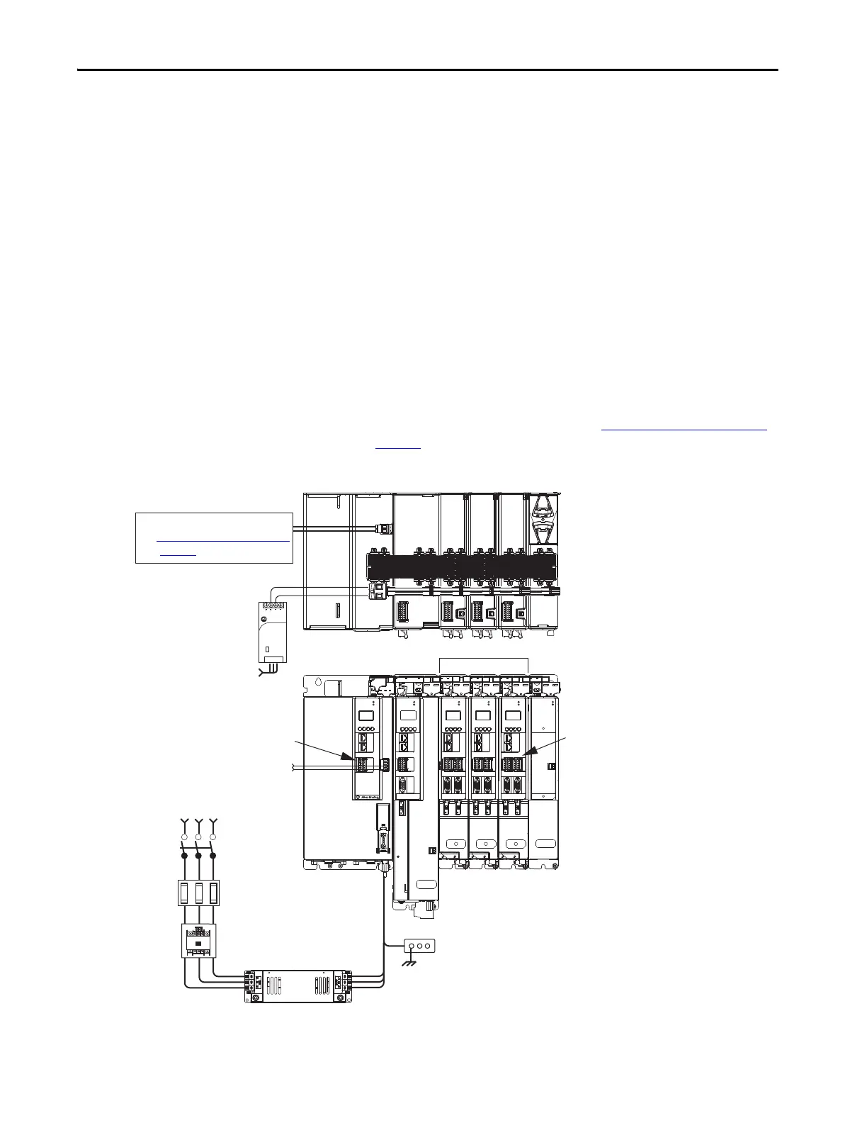
Typical Regenerative Bus Configuration Examples
In this example, the inverter modules are mounted to the right of the
regenerative bus supply. One single-axis (inverter) module and three dual-axis
(inverter) modules support seven axes of motion. Other features include:
• Digital inputs are wired to sensors and the control circuitry at the IOD
connectors.
• The contactor enable relay protects the regenerative bus supply in the
event of shutdown fault conditions.
• The DC-bus conditioner module is required when the combined motor
cable length exceeds 400 m (1312 ft). See Accessory Module Selection
on page 59
for more information on accessory module requirements.
Figure 5 - Typical Shared DC-bus Installation (mounted left to right)
(1) The regenerative bus supply can be left or right of the inverters. Further, we recommend that the highest inverter power ratings
are positioned closest to the regenerative bus supply and in decreasing order leading away from the regenerative bus supply.
1606-XL
Power Supply
Input
Allen-Bradley
MOD
NET
MOD
NET
MOD
NET
1
I/O
6
5
10
2
1
2
1
2
1
1
I/O-A
6
510
1
I/O-B
6
510
UFB
UFB-A UFB-B
UFB-A UFB-B
D+
D-
D+
D-
D+
D-
MF-A MF-B MF-A MF-B
D+
D-
MBRK
+
-
DC+
D+
D-
MF
SB+/NC
NC
19
8
16
19
8
16
19
8
16
1
I/O-A
6
510
1
I/O-B
6
510
S1A
SCA
S2A
SB-
NC
NC
SB+/NC
NC
S1A
SCA
S2A
SB-
NC
NC
SB+/NC
NC
S1A
SCA
S2A
SB-
NC
NC
MOD
NET
2
1
1
I/O
6
5
10
OK+
OK–
EN–
EN+
DC–
MOD
DC BUS
MODULE
STATUS
MOD
NET
2
1
UFB-A UFB-B
D+
D-
MF-A MF-B
D+
D-
1
I/O-A
6
510
1
I/O-B
6
510
19
8
16
SB+/NC
NC
S1A
SCA
S2A
SB-
NC
NC
Active Shunt (optional component)
See External Active-shunt Connections
on page 183
for more information.
Magnetic Contactor (M1) Control String
1606-XLxxx
24V DC Control, Digital Inputs, and
Motor Brake Power (customer-supplied)
AC Input Power
Kinetix 5700 Servo Drive System
(front view)
Shared-bus connection system for DC-bus and
24V DC control power.
Kinetix 5700 Servo Drive System
(top view)
Line Disconnect
Device
324…506V AC
Three-phase Input Power
Circuit
Protection
Magnetic (M1)
Contactor
Bonded Cabinet
Ground Bus
Converter Digital Inputs
Inverter Digital Inputs
Shared DC-bus Power
Shared 24V Control Power
(24V shared-bus connection system is optional)
Single-axis
Inverter
Dual-axis Inverters
Regenerative Bus Supply
(1)
DC-bus Conditioner
Module
2198-DBRxx-F
AC Line Filter
(required for CE)
 Loading...


