Rockwell Automation Publication 2198-UM002G-EN-P - February 2019 65
Plan the Kinetix 5700 Drive System Installation Chapter 2
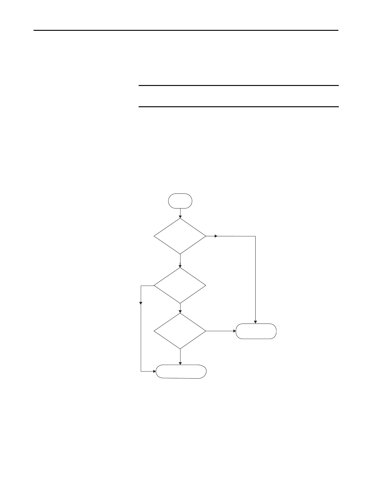
Accessory Module Flowcharts
The following flowcharts are designed to help you determine the minimum
number of accessory modules that are needed for your application.
In this flowchart, a 2198-Pxxx DC-bus power supply or 2198-RPxxx
regenerative bus supply supplies DC-bus power to a single cluster of drives.
System variables that you need to know include the following:
• The type of AC to DC converter used
• The input power ground configuration
• The total motor cable length
Figure 34 - Single-cluster Drive System
IMPORTANT Specific system demands can justify additional accessory modules based on
the previously mentioned benefits.
<400 m
(1312 ft)
≥400 m
(1312 ft)
What type of AC to DC
converter is used?
Start
Is this an impedance
grounded system?
DC-bus Conditioner Module
What is the total motor
cable length?
No accessory
modules required.
DC-bus Power
Supply
Regenerative Bus
Supply
Yes
No
 Loading...


