Rockwell Automation Publication 2198-UM002G-EN-P - February 2019 399
Size Multi-axis Shared-bus Configurations Appendix C
System Sizing Example
This example shows how a single Kinetix 5700 drive cluster meets the total bus
capacitance, power cable length, and 24V DC current limitations.
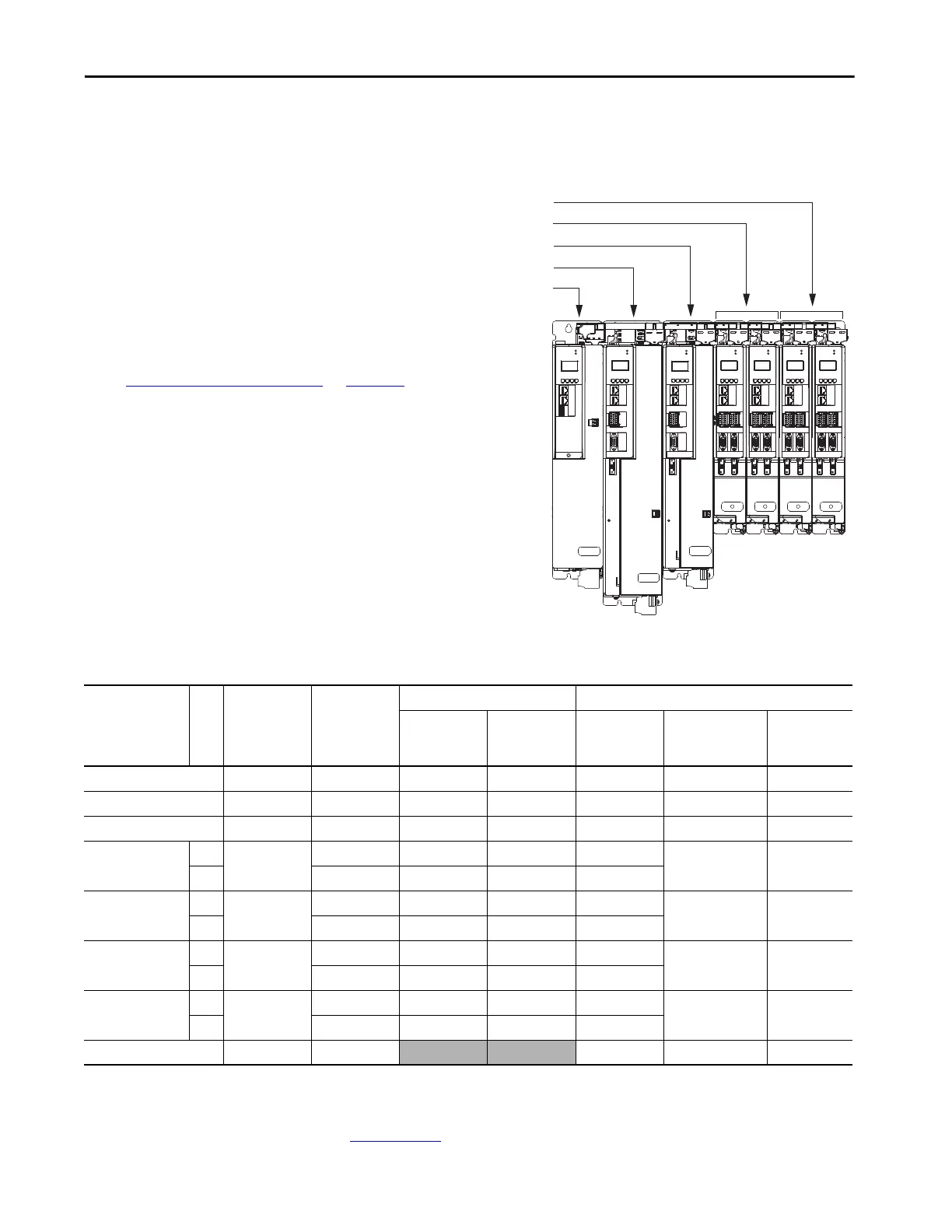
Figure 208 - Example DC-bus Group (single drive cluster)
Table 177 - System Sizing Example Data
For more information on motor and motor-brake specifications, refer to the
Kinetix Rotary Motion Specifications Technical Data, publication
KNX-TD001
.
MOD
NET
MOD
NET
MOD
NET
MOD
NET
2
1
1
4
I/O
I/O
2
1
2
1
2
1
1
I/O-A
6
510
1
I/O-B
6
510
1
I/O-A
61
I/O-B
6
510510
UFB
UFB-A UFB-B
UFB-A UFB-B
D+
D-
D+
D-
D+
D-
MF-A MF-B MF-A MF-B
D+
D-
MBRK
+
-
16
510
D+
D-
MF
MOD
NET
2
1
I/O
UFB
D+
D-
MF
MBRK
+
-
MOD
NET
MOD
NET
2
1
2
1
1
I/O-A
6
510
1
I/O-B
6
510
1
I/O-A
61
I/O-B
6
510510
UFB-A UFB-B
UFB-A UFB-B
D+
D-
D+
D-
D+
D-
MF-A MF-B MF-A MF-B
D+
D-
16
510
2198-D006-ERSx Dual-axis Inverters
2198-D020-ERSx Dual-axis Inverters
2198-S086-ERSx Single-axis Inverter
2198-S160-ERSx Single-axis Inverter
2198-P208 DC-bus Power Supply
In this example, only 1 drive cluster defines the DC-bus group.
• Maximum motor power cable length: 1200 m (3937 ft). See
Drive to Motor Cable Lengths
on page 158 for additional
motor power cable-length limitations.
– Total motor power cable length is 337 m (1106 ft)
• Maximum supported capacitance: 13,000 μF
– Total system capacitance is 4840 μF
– External bus capacitance is 4840-2050=2790 μF
• Maximum 24V DC control power current: 40 A
– Total 24V DC control power current is 20.3 A
– The Coil Current column shows how much of the 24V
current is consumed by the motor brake circuit.
All of the total system values are within the acceptable range.
DC-bus Group
Cat. No.
Axis
Internal
Capacitance
μF
Cable Length
m (ft)
Servo Motor 24V DC Control Power Current Calculations
Servo Motor
Cat. No.
Brake Option
Yes /N o
Brake Current
@ 24V DC
A
24V Current
(non-brake motor)
A
DC
Total Current
A
2198-P208 2050––––1.9 1.9
2198-S160-ERSx 1120 50 (164) MPL-B980E No – 4.6 4.6
2198-S086-ERSx 560 90 (295) MPL-B660F Yes 2.1 4.6 6.7
2198-D020-ERSx
A
390
20 (66) VPL-B1152F No –
1.4 1.4
B 15 (49) VPL-B1152F No –
2198-D020-ERSx
A
390
9 (30) VPL-B1003C Yes 0.50
1.4 2.4
B 90 (295) VPL-B1003C Yes 0.50
2198-D006-ERSx
A
165
9 (30) MPL-B310P Yes 0.50
1.4 1.9
B 9 (30) MPL-B310P No –
2198-D006-ERSx
A
165
15 (49) MPL-B310P No –
1.4 1.4
B 30 (98) MPL-B310P No –
Totals 4840 337 (1106)
3.6 16.7 20.3
 Loading...


