398 Rockwell Automation Publication 2198-UM002G-EN-P - February 2019
Appendix C Size Multi-axis Shared-bus Configurations
You must obtain the wire resistance value from the wire manufacturer.
Resistance values used below are only examples.
3. Determine if the voltage supplied to the drive system is within its
required input-voltage range; 24V ±10% (21.6…26.4V DC).
In this example, increasing the wire gauge to 6 mm
2
(10 AWG) is one
way to lower the voltage drop. See 24V Control Power Evaluation
on
page 49
for additional suggestions.
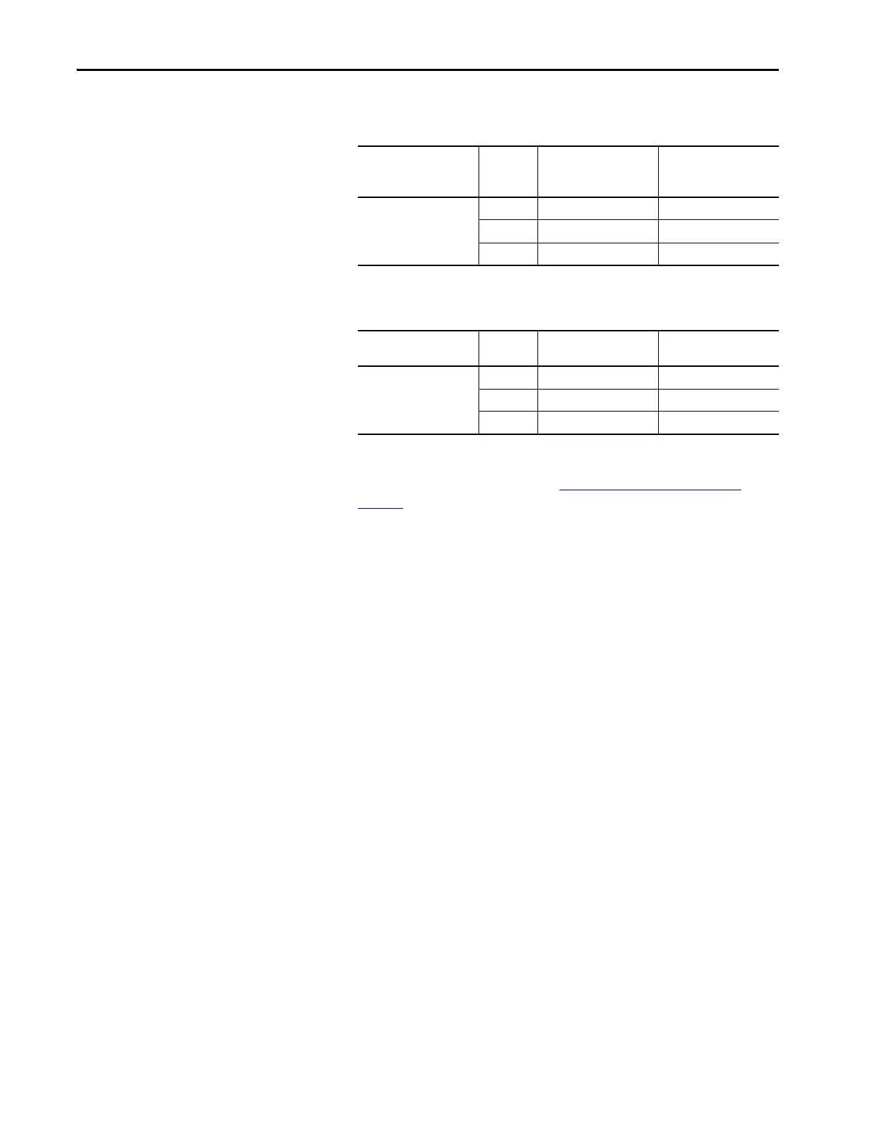
Wire Length
Wire
Gauge
mm2 (AWG)
Calculation Voltage Drop
21.3 m (70 ft)
1.5 (16) 22.9 A • 0.281 Ω 6.43V
4.0 (12) 22.9 A • 0.111 Ω 2.54V
6.0 (10) 22.9 A • 0.070 Ω 1.60V
Wire Length
Wire
Gauge
Calculation Applied Voltage
21.3 m (70 ft)
1.5 (16) 24V – 6.43V 17.57V (insufficient)
4.0 (12) 24V – 2.54V 21.46V (insufficient)
6.0 (10) 24V – 1.60V 22.40V (acceptable)
 Loading...


