Rockwell Automation Publication 2099-UM001D-EN-P - December 2012 113
Configure and Startup the Kinetix 7000 Drive System Chapter 5
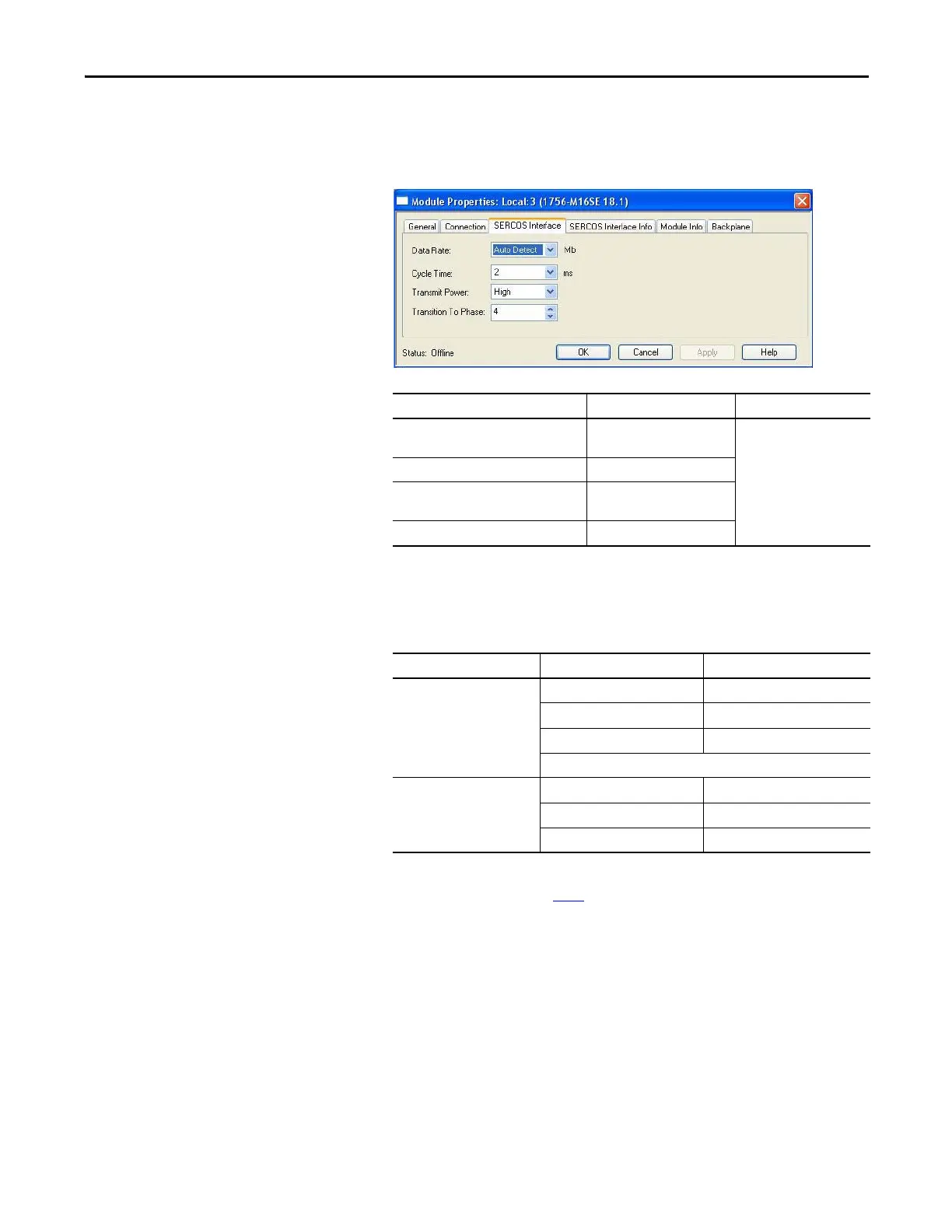
Your new module appears under the I/O Configuration folder in the
Controller Organizer and the Module Properties dialog box opens.
6. Click the SERCOS Interface tab and reference the table below.
7. Verify that the Data Rate setting matches DIP switches 2 and 3
(communication rate) as set on the drive, or use the Auto Detect setting.
8. From the Cycle Time pull-down menu, choose the Cycle Time according
to the following table.
9. Verify that the Transmit Power setting (high) matches the Optical Power
DIP switch 1 as set on the drive.
10. Enter the Transition to Phase setting.
The Transition to Phase default setting is 4 (phase 4). The Transition to
Phase setting stops the ring in the phase specified.
11. Click OK.
12. Repeat steps 1...11 for each SERCOS module.
Logix SERCOS Module Number of Axes Data Rate
1756-M03SE or
1756-L60M03SE
Up to 3
4 or 8 Mbps
1756-M08SE Up to 8
1756-M16SE or
1784-PM16SE
Up to 16
1768-M04SE Up to 4
Data Rate Number of Axes Cycle Time
4 Mbps
Up to 2 0.5 ms
Up to 4 1 ms
Up to 8 2 ms
No support for axes 9...16
8 Mbps
Up to 4 0.5 ms
Up to 8 1 ms
Up to 16 2 ms
The number of axes/module is limited to the number of axes as
shown in step 6
.
 Loading...


