164 Rockwell Automation Publication 2099-UM001D-EN-P - December 2012
Appendix B Interconnect Diagrams
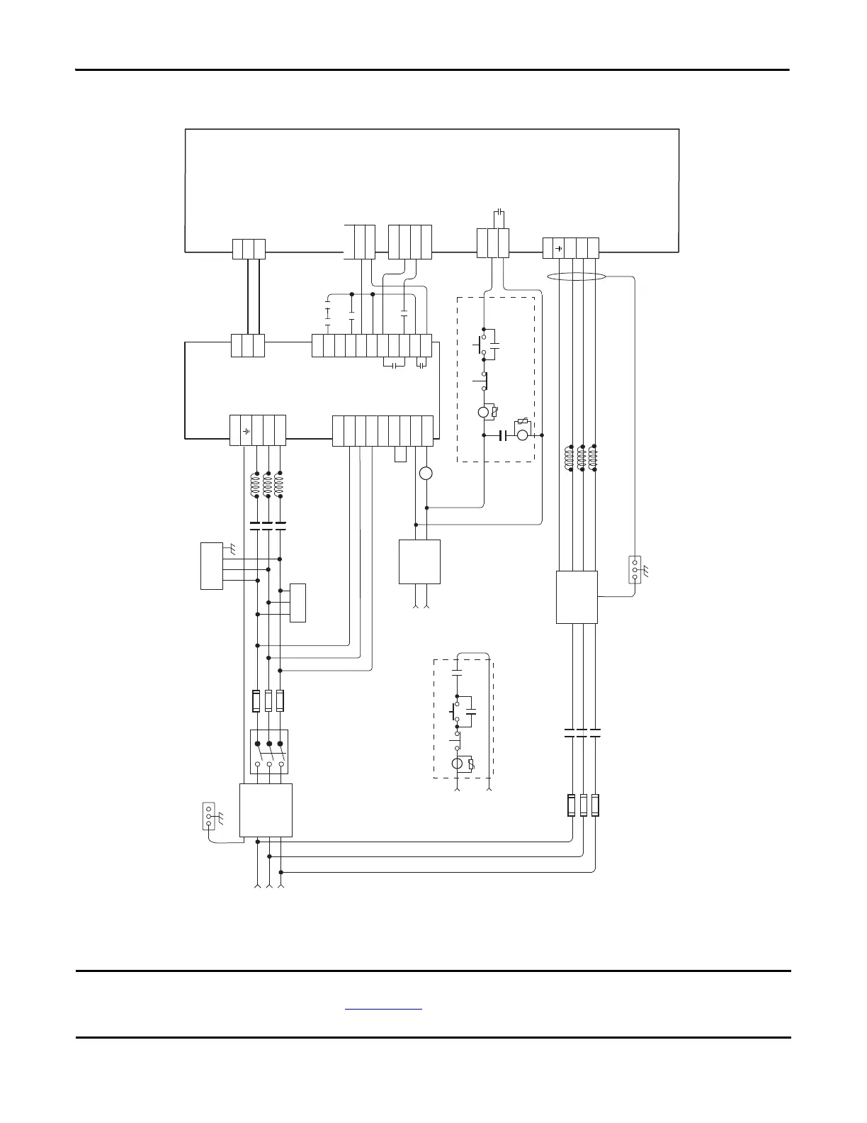
Figure 73 - Kinetix 7000 Drive AC Powered with a 8720MC-RPS065BM Regenerative Power Supply
This configuration requires the power regenerative mode settings as described in the 8720MC Regenerative Power Supply
Installation Manual, publication 8720MC-RM001
, and setting of the power tab in RSLogix 5000 software is set to the
appropriate bus regulator catalog number. Common mode capacitors should be disconnected on DC common bus drives.
STOP* START (RPS On)*CR1*
CR1*
E/N
R S T
MC
STOP* START (Drive Main Power On)*
CR2*
CR2*
CR2*
M1*
Note 4
L1
L2
L3
TB1
L1 AUX
L2 AUX
L3 AUX
PR1
PR2
PR3
MC1
MC2
TB2
TB1
DC+
DC-
MC
RST
PWR
0V
24V
COM
IP
RDY
FR
FR
TB3
5
6
PE
R
S
T
8
7
TB
REGEN COM
REGEN OK
GPIO
DC+
DC-
TB
GPR2+
GPR
*120V AC
or 24V DC
L1
L2
L3
M1*
GPR2-
Drive Stop-Start String*
*Bonded Cabinet
Ground Bus
*120V/240V AC
or
24V DC
*Line Reactor
(8720MC for
RPS unit)
RPS Stop-Start String*
*Bonded Cabinet
Ground Bus
* Indicates User Supplied Component
*Three-phase Input
(+10/-15%)
380V AC RMS, 50 Hz
or 460V AC RMS, 6 Hz
See Note 1
*Line Reactor
(1321-3R type, 3% compatible
with Kinetix 7000 drive)
*Three-phase Contactor
(M1 in Control String)
*Circuit
Breaker
* Varistor
*Input
Fusing
* Single-
phase
AC Line
Filter
*Harmonic
Filter
CR1*
Kinetix 7000 Drive
2099-BMxx-S
DC Bus
Connections
Control
Stop String
See Note 8
AC Input
Connections
*MC
AUX
*M1
AUX
* Three-phase
AC Line Filter
*Three-phase
AC Line Filter
24 V ENABLE
ENABLE
24V COM
IOD
1
2
Three-phase
Contactor (MC)
360° Shielding of Power Wiring
Required to Comply with
EMC Requirements
Line Contactor
(M1 on Stop String)*
Additional connections required,
but not shown in this diagram:
1. +24V DC Control Power
2. Motor Feedback, Brake (if used),
and Power
3. Drive I/O and Communications
Power
Connections
*Motion Control
Stop-Start String
(from PLC or other
control string)
Regenerative
Power Supply
8720MC-RPS065BM
Fault Relay
Contact
*Input
Fusing
See Note 3
Motion
Control I/O*
See Note 11
 Loading...


